


MSP430 Launchpad Tutorial - Part 1 - Basics
TI's LaunchPad is a complete MSP430 development environment: all you have to do is download and install CCS IDE (login required), connect your G2231-ready LaunchPad to your computer with the included mini-usb cable, and you are ready to code!
Quick Links
- Part 1: MSP430 Launchpad Tutorial - Part 1 - Basics
- Part 2: MSP430 Launchpad Tutorial - Part 2 - Interrupts and timers
- Part 3: MSP430 LaunchPad Tutorial - Part 3 - ADC
- Part 4: MSP430 LaunchPad Tutorial - Part 4 - UART Transmission

So, let's see how to start a new project in Code Composer Studio. This IDE is derived from Eclipse, so if you used it before you shouldn't have much problems.
We'll write a simple program that will toggle a led when we press the on-board button.
Go to New->CCS Project

Give a name and a destination folder to your project, then click "Next". Be sure to select "MSP430" in the next window, then go ahead. Don't care about the "Additional Project Settings" window for now, and click "Next". In the "Project Settings" window, be sure to have everything set like this picture.
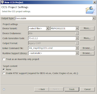
In the "Device Variant" field, select the correct MCU you have installed on your LaunchPad, then click "Finish".
Now we have to add a "main.c" file to our project. Right-click on your project name (note that it is in bold and has "Active - Debug" tags, meaning it will be the main project that will be compiled and debugged later on). Select "New->Source File".

Call it "main.c" then click finish. Now we are ready to add some real code!
Our first line of code will be this
#include "msp430g2231.h" //Contains definitions for registers and built-in functions
With this we include the definitions of registers and built-in functions for the MSP430G2231 e.g. if you used the other chip, the G2211, you had to include"msp430g2211.h" header file.
Next, we have the main routine.
int main(void)  //Main program
{
 WDTCTL = WDTPW + WDTHOLD; // Stop watchdog timer

 P1DIR |= BIT0; // Set P1.0 to output and P1.3 to input direction
 P1OUT &= ~BIT0; // set P1.0 to Off
 P1IE |= BIT3; // P1.3 interrupt enabled
 P1IFG &= ~BIT3; // P1.3 interrupt flag cleared

 __bis_SR_register(GIE); // Enable all interrupts

 while(1) //Loop forever, we'll do our job in the interrupt routine...
 {}
}
It's quite a mere "setup" routine, as we don't do nothing that involves the led toggleing.
WDTCTL = WDTPW + WDTHOLD;
With this line, we stop the "Watchdog timer": it is typically used to reset the MCU after a certain amount of time, to prevent deadlocks and infinite loops. In most examples, you will see that the watchdog timer is stopped during the first line of code, to avoid unwanted resets.
P1DIR |= BIT0;
With this instruction, we set the P1.0 pin (which is connected to the red led on the LaunchPad) to the output direction. In the MSP430 architecture, P1DIR is a 8-bit register that controls the i/o direction of the Port 1 pins. If you set a bit to 0, it is configured as an input, otherwise it is an output. The BIT0 constant is simply the 0x01 hex number, so you do this :
P1DIR before        00000000+
BIT0                00000001=
P1DIR after         00000001
This way, all the Port1 pins are set to input direction, except for P1.0 which is our led.
P1OUT &= ~BIT0;
Whit this,we resetthe P1.0 output . In fact, the P1OUT register controls all the output pins: if you put a bit to 1 (by or-ing the P1OUT register with the right numeric constant BIT0, BIT1...), the relative output pin is set on HIGH logical level, otherwise (by and-ing the P1OUT register with the inverted numeric constant) it is set on a LOW level.
P1IE |= BIT3; // P1.3 interrupt enabled
P1IFG &= ~BIT3; // P1.3 interrupt flag cleared
With these two instruction, we enable the interrupt on the P1.3 input pin (the on-board button).
What is an interrupt? Well, this is not the rigth time, but for now I'll you only have to know that this two lines of code allows the chip to know when the button has been pressed, even if he is doing other things (like calculations, delays ecc...). The P1IE register is used to enable interrupts on an input pin (it works like the P1DIR e P1OUT registers), and the P1IFG register is used to know if the desired event (in this case the press of the button) has happened (then the relative bit is set to 1) or not (the bit is set to 0).
__bis_SR_register(GIE);
With this built-in function, we enable all the interrupts by setting the GIE (Global Interrupt Enable) bit in the Status Register of the MSP430G2231. This function is also used to enter Low-Power modes, but this will be covered in a future tutorial.
while(1) {}
Finally, we enter an infinite-loop, as we have nothing more to do in the main function.
In fact, we will actually toggle the led in the "Port 1 interrupt service routine". This routine is called every time the state of a interrupt-enabled P1 pin changes from high to low (the button on the LaunchPad is active-low).
#pragma vector=PORT1_VECTOR
__interrupt void Port_1(void)
{
    P1OUT ^= BIT0;  // Toggle P1.0
    P1IFG &= ~BIT3; // P1.3 interrupt flag cleared
}
The first line of this function (P1OUT ^= BIT0;) toggles the pin state by xor-ing it. Then the Interrupt flag is set back to 0 in order to listen for another interrupt.
Now we are ready to launch the code on CCS.
Be sure to have the LaunchPad connected to your PC, then press the little green-bug button on the IDE to compile, download the code and enter the debug perspective.

Then press the "Play" button to start execution, the "Stop" button to exit debugging and the "Chip" button to reset the board.

If everything went well, you should see that if you press the on-board button, the red led will turn on and off.
If so, congratulations! You have built your first MSP430 program!
Here's the complete code of this example:
#include "msp430g2231.h"  //Contains all definitions for registers and built-in functions
int main(void)  //Main program
{
   WDTCTL = WDTPW + WDTHOLD; // Stop watchdog timer

   P1DIR |= BIT0; // Set P1.0 to output and P1.3 to input direction
   P1OUT &= ~BIT0; // set P1.0 to Off
   P1IE |= BIT3; // P1.3 interrupt enabled
   P1IFG &= ~BIT3; // P1.3 interrupt flag cleared

   __bis_SR_register(GIE); // Enable all interrupts

   while(1) //Loop forever, we'll do our job in the interrupt routine...
   {}
}
#pragma vector=PORT1_VECTOR
__interrupt void Port_1(void)
{
    P1OUT ^= BIT0;  // Toggle P1.0
    P1IFG &= ~BIT3; // P1.3 interrupt flag cleared
}
That's all for now. The next tutorial will focus on Timers and Interrupts.
Happy Coding!


- Comments
- Write a Comment Select to add a comment
#include "msp430F5529.h" //Contains definitions for registers and built-in functions
int main(void) //Main program
{
WDTCTL = WDTPW + WDTHOLD; // Stop watchdog timer
P1DIR |= BIT0; // Set P1.0 to output
P1OUT &= ~BIT0; // set P1.0 to Off
P2DIR &= ~BIT1; // Set P2.1 to input
P2REN |= BIT1; // Enable pullup resistor of P2.1 (default: GND)
P2OUT |= BIT1; // Set pullup resistor to active (+3.3V) mode
P2IE |= BIT1; // P2.1 interrupt enabled
P2IFG &= ~BIT1; // P2.1 interrupt flag cleared
__bis_SR_register(GIE); // Enable all interrupts
while(1) //Loop forever, we'll do our job in the interrupt routine...
{}
}
#pragma vector=PORT2_VECTOR
__interrupt void Port_2(void)
{
P1OUT ^= BIT0; // Toggle P1.0
P2IFG &= ~BIT1; // P2.1 interrupt flag cleared
}
Have you executed this 'part 1' code succesfully?
My Launchpad don't recognize the push button press. What about your board?
Thanks a lot.
On my board there aren't mounted Rpull up and anti debouncing capacitor.
I add on code the pull up on the push button
P1REN |= BIT3; // Enable Pull Up on (P1.3)
, and I add (pheraps not necessary)
P1IES |= BIT3; // P1.3 Hi/lo edge
to select the interrupt activation' edge.
Really.
I too am working with a 2553 and didn't know why I wasn't getting the expected result.
The pull up resistance fix is really waht I needed, thanks.

Nice beginner example. It would be even better if the example worked. Be sure to read the comments about adding the pull up resister to allow the button to work properly. You'll still have button bounce problems, but that's ok for a simple example like this as long as you understand the erratic behavior is a bounce problem

I'm a tad late to the MSP430 party. Old processor but seems still relevent. Thanks for the tutorial. Well written.
Dave
__interrupt void Port_1(void)
{
P1OUT ^= BIT0; // Toggle P1.0
P1IFG &= ~BIT3; // P1.3 interrupt flag cleared
}
This code is showing syntax error and other declaration errors too...please correct it

thanks,
awesome and informing tutorial
I try your code using Launchpad with MSP430G2553.
Red led is still on P1.0 and pushButton is still on P1.3.
If I move my finger near the button (near about 1mm or 2) the led change state, if I press the button with a plastic pen, nothing happens.
Could be the pin set as capacitive touch pin?
If yes, how can I disable it? (I try only to set to 0 control bit P1SEL and P2SEL)
If no, what it could be?
Nice article, good job! Thanks
On my board there aren't mounted Rpull up and anti debouncing capacitor.
I add on code the pull up on the push button
P1REN |= BIT3; // Enable Pull Up on (P1.3)
, and I add (pheraps not necessary)
P1IES |= BIT3; // P1.3 Hi/lo edge
to select the interrupt activation' edge.
just purched MSP430F5529LP and i am trying to write a code using switch button.
in the following code a defined the switch as an input (P1.1 = 0 - by default)
void main()
{
WDTCTL = WDTPW + WDTHOLD; //stop watch dog timer
P1DIR |= 0x01; // red LED output
P1REN |= 0x02; //enable pullup/down
while(1)
{
//do something
}
}
somehow, as i debbuged this code, P1IN remains constant as i press the switch(P1IN doesnt change according to the switch pressing)
I am quiet lost about it cause i know that PxIN is readonlt register that gives indication about the inputs.
thanks!
Code:
#include
int main(void) {
WDTCTL = WDTPW | WDTHOLD; // Stop watchdog timer
P1DIR |= BIT6;
P1OUT &=~BIT6;
P1REN |= BIT3;
P1IE |= BIT3;
P1IFG &=~BIT3;
__bis_SR_register(GIE);
while(1){
}
}
#pragma vector=PORT1_VECTOR
__interrupt void Port_1(void){
P1OUT ^= BIT6;
P1IFG &=~BIT3;
}
Hello,
What does this line means?
#pragma vector=PORT1_VECTOR
And how does the MSP430 knows that it should jump to this function when the interrupt is set?
Thanks for sharing this tutorial. I m beginer and just little bit confusion about time about blinking of led as we have given infinite loop so how much it takes time in glow on and off?Because here we are not defining any clock or timer.
Friends send me the msp430 c-programm
1) Division of two numbers
2) Find largest element in array
3) BCD to ASCII and vice versa
4) ASCII to decimal and vice versa
5) hexa to decimal and vice versa
To post reply to a comment, click on the 'reply' button attached to each comment. To post a new comment (not a reply to a comment) check out the 'Write a Comment' tab at the top of the comments.
Please login (on the right) if you already have an account on this platform.
Otherwise, please use this form to register (free) an join one of the largest online community for Electrical/Embedded/DSP/FPGA/ML engineers:


