


Feedback Controllers - Making Hardware with Firmware. Part 3. Sampled Data Aspects
Some Design and Simulation Considerations for Sampled-Data Controllers
This article will continue to look at some aspects of the controllers and electronics needed to create emulated physical circuits with real-world connectivity and will look at the issues that arise in sampled-data controllers compared to continuous-domain controllers. As such, is not intended as an introduction to sampled-data systems.
- Part 1: Introduction
- Part 2: Ideal Model Examples
- Part 3: Sampled Data Aspects
- Part 4: Engineering of Evaluation Hardware
- Part 5: Some FPGA Aspects
It will also document some specific electronic devices and their key parameters for a practical design, which updates an original design based on a Sharc DSP device, to a floating-point centric FPGA solution.
As ever, it should be noted that equivalent arrangements/topologies are possible and that any examples shown may not necessarily be the best or most complete solution.
Motivation for a Sampled-Data Controller
We have previously considered some ideal controller designs in the continuous s domain and described some advantages of using a controller made from small-signal components along with an amplifier in a feedback arrangement to provide emulated electronic/electrical circuits. However, that was really just a concept step to a more universal solution.
If a controller could produce the required characteristics via mathematics/algorithms/firmware, then we would now get a flexible capability to create arbitrary (within limits) circuits along with say non-linear, time-varying & for example frequency-varying resistance characteristics not conveniently created in analogue hardware.
s vs z, MATLAB vs Simulink and an important difference
So far, we have formulated controller examples as continuous s domain transfer functions. When we move to a sampled-data z domain solution we have a lot more theoretical and practical issues to consider, the 1st of which might be that, given an s domain characteristic, how do we get an equivalent, discrete, z domain description that gives us the same characteristic ?. MATLAB provides a method called c2d with various method options, to convert s domain functions into equivalent characteristic z domain functions. For closed-loop applications, the First Order Hold(FOH) or Ramp-invariant method is recommended.
Example for comparison of s,z,MATLAB and Simulink responses
Consider the previous example now denoted Gs and its discrete version Gz
MATLAB
opts = bodeoptions('cstprefs');
opts.FreqUnits = 'Hz';          % change the bode options to Hz
s = tf('s');                    % declare the s operator
R1 = 100;                       % Series Part of Z1
R2 = 300;                       % Parallel Resistive Part of Z1
C  = 100e-9;                    % Parallel Capacitive Part of Z1
%RL = 400;                       % Load/Feed Resistor
Z1Para = 1/((1/R2) + ( C*s)) ;  % Parallel Part of Z1
Gs = R1 + Z1Para;               % Reference impedance for emulation
z = zpk('z',0.0000005);           % declare the z operator
Gz = c2d(G,0.0000005,'foh');      % discretise at 2Msps
% zoh,foh,impulse,tustin,matched  - method options available
bodeplot(Gs,Gz,{1,10000000},opts)  % show Gs & Gz
grid on  % grid on
Fig 1. MATLAB script for previous example Gs and its equivalent discrete version Gz sampled at 2Msps.
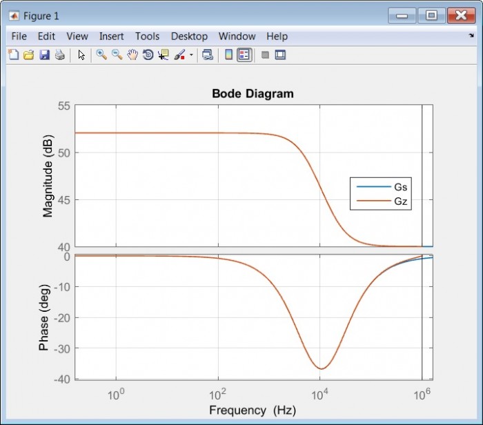
Fig 2. The resulting MATLAB plots for s (Gs) and z (Gz) domain functions.
As we can see the MATLAB s and z domain plots are coincident to a high degree of accuracy, as desired.
Simulink
Switching for a moment to the time-domain, here is the set-up for a Simulink model of the s domain and z domain example.
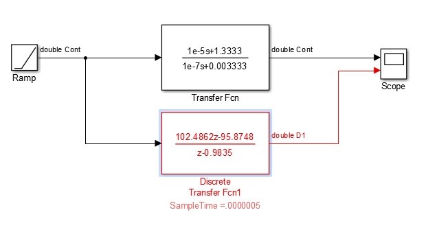
Fig 3. Simulink Model of the s and z domain example with a Ramp input.
The z domain transfer function is the result of using the FOH or Ramp-invariant option in the MATLAB c2d function and as the name suggests, the z transform response should be identical to the s domain response for a ramp input signal at the sample points.
Here are the resulting scope plots.
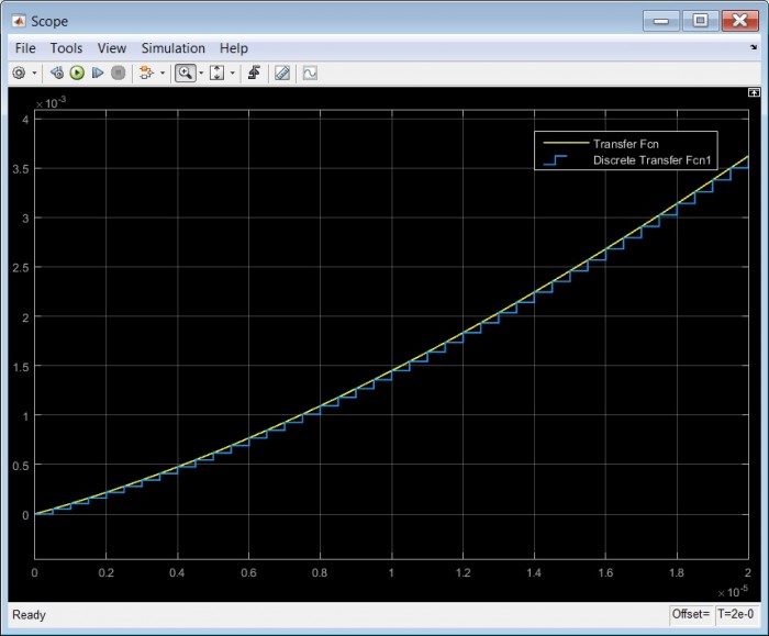
Fig 4. Simulink time-domain plots for s and z domain example with Ramp input.
The result is as expected, the curves are coincident at the sample points.
MATLAB vs Simulink
Simulink does not provide a Bode plotter as standard so a time-domain method based on sine-wave excitation and IQ measurement of this excitation and the corresponding o/p signal was constructed. This is not necessarily efficient , but it works.
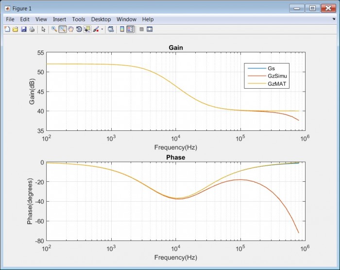
Fig 5. MATLAB Bode Plots of Reference Gs (Blue, hidden under Yellow), GzMAT(Yellow) and Simulink Bode Plot of GzSimu (Orange).
So now we have an apparent contradiction, The MATLAB Bode plot of GzMAT follows the Gs reference closely whereas the Simulink Bode Plot for GzSimu falls away from the reference at higher frequencies.
In fact we can see from the time-domain plot in Fig 4 that the average GzSimu waveform is lagging the Gs reference. As many will know, the answer to this apparent contradiction is that the MATLAB Bode plot for GzMAT considers only the sample point instances, which is an accurate but rather abstract case. The home-made Simulink Bode plot shows the true nature of the sample system output by considering the entire waveform, not just the sample points.
This is the first of our non-ideal effects caused by the move to a sampled-data controller and it is due to the holding effect of the DAC which is present even if the DAC provides perfect outputs at the sample points. This effect is know as zero order hold (ZOH).
A list of issues affecting the performance of sampled-data controllers.
Having spent a bit of time looking at the ZOH effect and noting that the MATLAB Bode plot does not include it, here is a collection with notes, of other issues that need consideration when designing a sampled-data controller and how those issues have been accommodated in a practical design.
| Issue | Comment | Anticipated Value/Solution |
Contingency Plan |
| Sample Rate |
Limits upper frequency of effective digital signal processing. Limited by ADC, FPGA capability and other latencies |
Between 2Msps and 15Msps with Cyclone V FPGA and LinearTech ADC |
Faster Cyclone 10 GX FPGA |
| ADC/DAC Bits |
The more bits available, the greater the dynamic range and lower the quantisation noise |
16 Bit LinearTech ADCs and DACs | 18 bit LinearTech ADC |
| ADC Latency |
Latency limits the upper frequency for closed-loop digital signal processing. SAR ADCs have no pipeline delay and are available in 16/18 bits and are simple to drive and are modestly priced. Flash ADCs are typically fewer bits, and their high throughput rate is often offset by pipeline latency. |
LinearTech 16 bit 15Msps SAR ADC |
More expensive lower latency ADC |
| ADC Anti-aliasing filter |
A filter may be required before the ADC to reduce the levels of interfering frequencies above the Nyquist frequency. Such filters add unwanted latency. |
A filter is included in the design. |
Additional filter options are available. |
| DAC ZOH effect |
This causes phase lag and amplitude droop at higher frequencies. |
Phase and Amplitude compensation. | |
| DAC Reconstruction filter |
The quantised DAC o/p can benefit from some filtering to remove unwanted higher frequencies. Such filters add unwanted latency. | A filter is included in the design. | |
| Mathematical Precision |
The precision of the mathematics for complex, multi-stage signal processing, affects the quality of the final signals at the output of the sample-data controller. High Precision mathematics may need to be traded for high speed, low latency operation. |
Cyclone V FPGA running single-precision floating-point mathematics. |
Fixed-Point Mathematics. Cyclone 10 GX FPGA. Multi-rate processes. |
| Filter Realisation |
There are a variety of structures and topologies for realising complex digital filters. Some structures offer better performance than others for noise and speed performance. Both FIR and IIR filters are anticipated but the IIR filter is likely to predominate. |
IIR Type II Transposed Biquads with optimal pairing of poles/zeros and optimal sequencing by frequency characteristic. |
Try alternative topologies. |
Automated Design and Due-Diligence on sampled-data controllers
A combination of MATLAB combined with Simulink has the ability to not only evaluate all the issues described above, but also the possibility to provide automated design processes to take a characteristic described at a high-level and then run the algorithms needed to to realise the detailed lower level filter structures and parameters.
Given the availability of the Altera/Intel DSP Builder package linking MATLAB with the Altera/Intel Quatus FPGA design suite, it is reasonable to expect that a complete end-to-end design process starting with a Performance Requirement via the Controller Design and through to the FPGA Design and Programming operation, could be constructed.
Why does the circuit emulator application require particularly demanding performance ?
There are a number of reasons that the controller performance needs to be exceptional for the circuit emulation application.
- Electronic circuits by their nature can operate a very high frequencies compared to say the dynamics of a closed-loop system including mechanical elements. Given that we would like to emulate circuits to as high a frequency as possible we require that our emulation feedback loop can operate accurately at those frequencies.
- The accurate emulation of electrical/electronic circuits requires that the controller is providing accurate amplitude and phase signals at every instant in time, not just steering towards an accurate settling point.
- Instrumentation grade emulated circuits require low noise and low distortion. These may well be at higher performance specifications when compared to other closed-loop applications.
Other Applications that require exceptional controller capabilities will be considered in a future article.
Key Devices designed into a practical evaluation unit
A technology evaluation platform has been designed for investigating arbitrary circuit emulators and the low- latency controllers required for their construction.
The initial device selection includes :-
| Function | Device |
Vendor |
| ADC | LTC2387- 16 or 18 bit | LinearTech(ADI) |
| DAC | LTC1668 | LinearTech(ADI) |
| FPGA | Cyclone V 5CEFA9F23C8N (potential for Cyclone 10 GX) |
Altera/Intel |
| Port Amplifier |
THS3201-EP (option for external high-voltage/current amplifier) |
TI |
For the record, I have no affiliation with any of the above mention vendors, just a keen interest in the application of science and engineering to practical applications.
Next up - will be a fuller description of the evaluation platform.


- Comments
- Write a Comment Select to add a comment
To post reply to a comment, click on the 'reply' button attached to each comment. To post a new comment (not a reply to a comment) check out the 'Write a Comment' tab at the top of the comments.
Please login (on the right) if you already have an account on this platform.
Otherwise, please use this form to register (free) an join one of the largest online community for Electrical/Embedded/DSP/FPGA/ML engineers:


