


Noise shaping
eywords: Quantization noise; noise shaping
A brief introduction to noise shaping, with firm resolve not to miss the forest for the trees. We may still stumble over some assorted roots.
Matlab example code is included.
Quantization
Fig. 1 shows a digital signal that is reduced to a lower bit width, for example a 16 bit signal being sent to a 12 bit digital-to-analog converter. Rounding to the nearest output value is obviously the best that can be done to minimize the error of each sample.
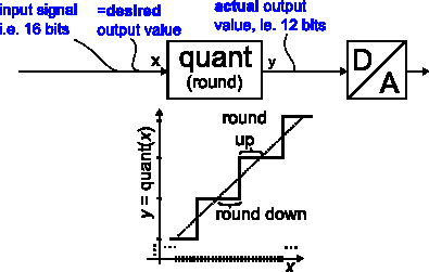
Figure 1: Quantization (reduction of bit width)
At least for noise-like signals (other signals may require dithering, which is out-of-scope here), the quantization error of each sample is independent, and the spectrum of the error is white. That is, it has equal power density at all frequencies.
Noise shaping can lower the quantization noise in some bandwidth of interest, but the price is always an increase in overall noise.
How does it work? The known quantization error of an output sample is used as the first sample of an arbitrary impulse response htarget, and the impulse response is completed by adding its remaining part later to the original signal, before quantization.
The impulse response htarget corresponds to a noise spectrum Htarget of my choice.
Figure 2 shows the impulse response htarget, scaled to match the instantaneous quantization error e with its first sample. Its remaining samples are then added to the future signal (before quantization).
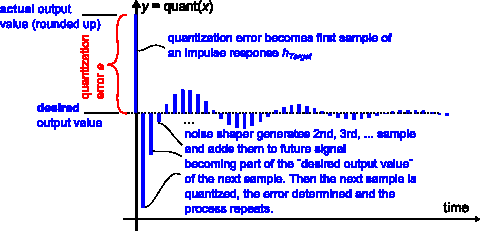
Figure 2: Noise shaping: Quantization error becomes the first sample of an impulse response
Figure 3 shows the block diagram of a noise shaper that implements this idea.
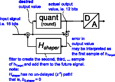
Figure 3: Block diagram of noise shaper
Conceptually, the quantization error of each sample is calculated by subtracting the quantizer output from the input. An actual implementation might simply use the truncated bits.
This quantization error is now considered to be the first sample of a desired noise impulse response htarget. It is sent to a digital filter Hshaper that generates all the remaining samples of htarget, which are then added to the future input signal.
Filter design
Htarget can be thought of as a digital filter that transforms random, white noise into the desired noise spectrum (it is also designed as a digital filter).
Hshaper is another filter closely related to Htarget: Given the first sample of htarget at its input, Hshaper outputs all future samples of htarget.
Hshaper can be derived from Htarget by normalizing it to the first impulse response sample, then subtracting this first sample. In other words: Scale to make its impulse response start with "1", then subtract "1" - now the impulse response hshaper starts with "0".
The calculation is straightforward if one remembers that the first output sample of an IIR filter depends only on b0, because all other coefficients refer to delay line contents, which are initially zero.
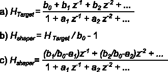
Figure 4: Derivation of noise shaper filter from targeted frequency response
Fig. 4 shows the calculation. Hshaper can be found by comparing coefficients of z-1, z-2 etc. between a) and c).
Hshaper has no undelayed path and thus acts as a unit delay that makes it possible to implement the feedback loop formed by filter and quantizer.
Fundamental limits
The noise shaper can enforce any arbitrary shape to the noise spectrum, but there is a catch: As Hshaper is normalized (divided) by the first sample of htarget, an excessive magnitude of the added noise shaping signal will result if htarget starts up too slowly. Typically, this rules out attempts to suppress noise over a wide bandwidth.
For the same reason, a minimum-phase frequency response in Hshaper seems advantageous, as it minimizes the delay of energy in the impulse response over one that is non-minimum-phase [4], and thus tends to have a higher first sample.
The Gerzon-Craven noise shaping theorem formalizes these insights.
To illustrate this fundamental limitation, Figures 5 and 6 show two example frequency responses. The first (Fig. 5) attempts noise rejection only over a narrow frequency span. The resulting impulse response is well-behaved, with a large first sample.
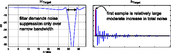
Figure 5: Attempt to suppress noise in a narrow bandwidth only (good)
The second frequency response (Fig. 6) attempts strong noise rejection over a much wider bandwidth. Its impulse response has a rather small first sample - barely visible in the plot - and normalizing this sample to "1" will cause the remaining impulse response to contribute a high level of unwanted noise, possibly achieving exactly the opposite of what was intended.
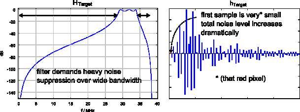
Figure 6: Attempt to achieve wide-band noise suppression (bad)
Example code
A Matlab / OctaveForge example is available for download (link at bottom of page). It designs an IIR bandstop filter for Htarget, as shown in Fig. 7, with a 4 MHz notch around 31 MHz at a sampling rate of 76.8 MSPS.
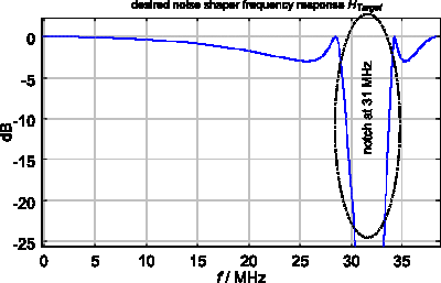
Figure 7: Example HTarget, an IIR filter design
The filter is then converted into a noise shaper (using equations from Fig. 4), and applied to quantize a random signal. The resulting quantization error spectrum is shown in Fig. 8 (magenta), together with the equivalent output of a conventional quantizer without noise shaping (red).
Quantization error in the stopband of the filter is clearly reduced, whereas the total quantization error (integrated over all frequencies) increases as expected.
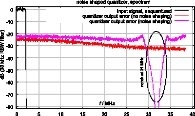
Figure 8: quantized output spectrum with and without noise shaping
Finally, Figure 9 shows input and output signals in the time domain.
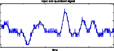
Figure 9: input and output waveform
Quantization, clipping and stability
Looking at Figure 9, it should not be surprising that the structure in Fig. 3 oscillates by design: The differential gain of the quantizer in the feedback loop approaches infinity for levels close to any switching threshold. This is acceptable, because the error caused by an unlimited stairstep quantizer never exceeds half a "stairstep" in either direction. For bounded input, also bounded output of the filter may be guaranteed.
A multi-bit signal can be dimensioned so that digital clipping is a rare or even impossible event. One could make a solid argument that the objective for the noise shaper is to manage quantization, not clipping. Noise shaping on a wide bitwidth is common for example for the word length reduction of audio signals [1], such as the final step in mastering for 16-bit CD audio.
Noise shaping is also used in applications, where clipping is part of normal operation (i.e. one-bit sigma-delta modulation). Now no amplitude limit to the quantization (clipping) error is enforced. The noise shaping filter suddenly finds itself embedded in an instable feedback loop without amplitude limit. Signal values "run away" and the structure becomes non-functional.
Further discussion of the clipping problem can be found in [2] at the end of section 1. The design of stable sigma-delta modulators is a well-researched topic, but out-of-scope here.
Summary
This brief article introduces noise shaping by considering quantization error as first sample of a designed impulse response. An example program is included.
Download
The program (Octave / Matlab) can be downloaded here . It requires this spectrum analyzer code snippet in the same folder.
References
[1] Hydrogen Audio: Noise shaping Wiki
[2] Why 1 bit Sigma-Delta conversion is unsuitable for High Quality applications


- Comments
- Write a Comment Select to add a comment
I am interested in this paper. Unfortunately, images for charts and formulas are not available. Can you please upload a PDF file or restore images.
Thank you.

Thanks, they got lost somehow. Images and code links should be back now (the spectrum analyzer file needs renaming, remove the auto-generated attachment number).
Hello Markus Nentwig, thanks for the post related to noise shaping. Here, the input resolution is down from 16 to 12. Can we do it opposite, I mean input resolution is 12 bit but the output should be 16 bit.
Thanks.
To post reply to a comment, click on the 'reply' button attached to each comment. To post a new comment (not a reply to a comment) check out the 'Write a Comment' tab at the top of the comments.
Please login (on the right) if you already have an account on this platform.
Otherwise, please use this form to register (free) an join one of the largest online community for Electrical/Embedded/DSP/FPGA/ML engineers:


