


Thermistor signal conditioning: Dos and Don'ts, Tips and Tricks
In an earlier blog entry, I mentioned this circuit for thermistor signal conditioning:

It is worth a little more explanation on thermistor signal conditioning; it's something that's often done poorly, whereas it's among the easiest applications for signal conditioning.
The basic premise here is that there are two resistors in a voltage divider: Rth is the thermistor, and Rref is a reference resistor. Here Rref is either R3 alone, or R3 || R4, depending on the gain setting.
This is only one possible circuit. There are many others, but please use the following guidelines.
Just to be clear, we're going to talk about using an NTC (negative-temperature coefficient) thermistor in an embedded system with an analog-to-digital converter (ADC) and a processor.
Don't:
- Don't linearize your analog circuitry
Linearization is the use of additional circuitry (usually 1-3 additional fixed resistors placed in series or parallel with the thermistor or reference resistor) to produce a voltage that is a more linear function of temperature. There are a number of application notes on linearization from manufacturers like Maxim, Microchip, and EPCOS.
In purely analog circuits, linearization is necessary. For example, thermocouple circuits often require cold-junction compensation to correct for errors caused by changing temperature of the "cold junction", which is where the thermocouple wires are attached to the signal conditioning circuitry. This often uses a thermistor, and the nonlinear response of a thermistor needs to be conditioned into a linear adjustment to the thermocouple amplifier.
In an embedded system using ADCs and a processor, linearization is both unnecessary and wasteful. Linearization comes at a cost. The sensitivity of voltage output is reduced, and there are more components involved, which means more opportunities for component tolerance to contribute to temperature error.
There is absolutely no reason why in such an embedded system, the processor should not do the linearization in software. There are some very simple and fast ways to handle the nonlinear conversion of ADC counts to temperature, which we'll discuss later.
- Don't use excess signal conditioning
One system I worked on was designed by a contractor, and had a linearization circuit which reduced the sensitivity of the thermistor output by about a factor of 10, followed by an amplifier circuit that amplified the thermistor output by a factor of 10 relative to a reference voltage. I looked at the schematic and shook my head.
Please realize that each stage of signal conditioning introduces the chance for errors.
In analog circuitry, component tolerances and noise sensitivity cause these errors: Resistors and capacitors have value tolerances. Op-amps have specs like offset voltage and current. ADCs have gain and offset errors, and integral and differential nonlinearity. (INL and DNL)
These all add up. My rule of thumb is that unless you keep things very simple, use good components, and design carefully, it is difficult to have net voltage errors below 1% of the ADC fullscale -- excluding the sensor itself, and this goes for any sensor, not just thermistors. If errors concern you, then you really need to anticipate what kind of errors to expect in your system, and find ways to deal with them.
For a basic resistor divider, you can use 0.1% resistors: these have really come down in price over the last 10 years -- a single 10K 0.1% 0603 resistor can be purchased from Digikey for $0.25, with prices of about $0.10 in 1K quantities. As far as op-amps go, so many manufacturers make CMOS op-amps with picoamp input currents that it's easy to forget about input current errors. Typical offset voltages are now in the 2-5mV range. For a buffering application in a 3.3V system this is about 0.1-0.2% of fullscale; applications with gains higher than 1 are worse and you may have to use more costly precision op-amps.
(In digital signal processing, there are no component tolerances or noise, but in each stage of computation there is an oppportunity to introduce errors when doing multiplication or division. PCs use double-precision (64 bits or more) to calculate math; embedded systems often limit this precision to 32-bit or 16-bit fixed point math. The errors are very small and predictable compared to the errors of analog signal conditioning, but they still exist.)
In any case, keep it simple and you'll save yourself trouble.
Do:
- Do understand your requirements
This is probably the most important and understated part of the design process, for any circuit, not just thermistors.
The three most important requirements for thermistor temperature sensing are:
- temperature sensing range
- temperature sensing resolution
- temperature sensing accuracy
Let's look at the "Z" curve for Quality Thermistors, in a voltage divider:
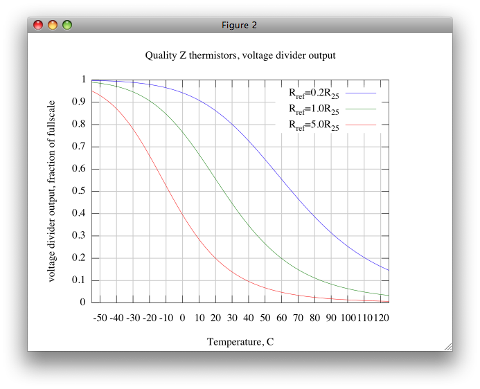 You'll typically find NTC thermistors in a 10K nominal resistance at 25 C. This nominal resistance at 25 C is an important parameter of the thermistor, which we'll abbreviate as R25. Shown above are the output voltages in a voltage divider (as a fraction of the total voltage across the voltage divider) where the reference resistor Rref is either 0.2R25, 1.0R25, or 5.0R25. (corresponding to 2K, 10K, and 50K for R25=10K) These curves are very easy to calculate from the manufacturer's thermistor curves: the voltage divider ratio α = Rth/(Rref + Rth) = 1 - Rref/(Rref+Rth).
You'll notice that for each reference resistor, there's a range of about 60-80 degrees C over which α drops from 0.9 to 0.1. Outside those ranges, the sensed voltage changes very little with temperature. So if your range of interest is, for example, 25 C - 100 C, you might want to use Rref of 0.2R25 and live with the low resolution in sensed temperature above and below that range. If you need to sense temperature over a wide range, you need to make a system that either can accurately read voltage to deal with the low sensitivity at cold and hot temperatures, or you need to switch Rref between ranges, like we talked about in my previous article (with the choice of either R3 alone, or R3 || R4).
Another way of looking at this circuit is to analyze the sensitivity itself (for those of you familiar with calculus, it's the first derivative with respect to temperature dα/dT):
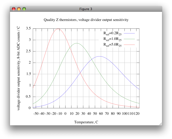
If you are using an 8-bit ADC, this graph shows the sensitivity (in counts per degree) of temperature sensing at various temperatures. Sensitivity and resolution are related: the more sensitive a circuit is, the higher resolution it provides. Quantitatively, the two are related inversely: 3 counts per degree means 0.33 degree resolution, whereas 10 counts per degree means 0.1 degree resolution. If you only need 1 degree C resolution, you're probably fine with an 8-bit ADC. If you need 0.1 degree C resolution, you'll want a 10-bit ADC, or you'll want a way to amplify ranges of the thermistor voltage.
Resolution is a distinct requirement from accuracy. A digital thermometer, even if it's off by 2 degrees C, can easily show you temperature in 0.1 degree steps: that's a resolution of 0.1 degree but an accuracy of 2 degrees C.
Accuracy is much more difficult to analyze, as it has many contributing factors, but the biggest cause is the accuracy of the thermistor itself. Many thermistors are specified with a 5% resistance tolerance at 25 C; the inherent temperature error is this relative accuracy divided by the thermistor's temperature coefficient. Quality Z's thermistor table shows a tempco of 4.4%/degree at 25 C, so 5% / 4.4% = 1.1 degree C accuracy.
In general, it is very difficult or expensive to get high accuracy thermistors without some sort of calibration step.
- Do use ratiometric circuits
A ratiometric circuit is one in which the ratio of voltages or currents is sensed, rather than their absolute values. Resistor dividers and Wheatstone bridges are both examples of ratiometric circuits. Sensors which use ratiometric circuits are ideal, because it means that the accuracy of the quantity you are sensing is independent -- or at least nearly independent -- of the accuracy of voltage or current references in your circuit. If a reference voltage or current has variation with time or temperature, so does the sensed voltage or current, and this variation cancels out when the ratio is calculated.
Nearly all ADCs and DACs are ratiometric as well: the sampled digital output of an ADC is the ratio of its analog input voltage to its reference voltage, and the analog output of a DAC is the fraction of its reference voltage selected by its digital input.
Three of the circuits I have mentioned (resistor dividers as a function of their resistances, ADCs, and DACs) are what I would call strongly ratiometric: the ratios of these circuits are unitless functions of resistance or voltage ratios, and they range from essentially 0 to essentially 1. In other words, the gain is almost exactly predictable. (ADCs and DACs have slight gain error, and resistor dividers of low values may have parasitic series resistance that causes errors, but otherwise their transfer functions are very close to 1.)
Watch out with your ADCs and DACs, though: some of them take in half-scale reference voltages, so there is an indirect gain of 2 somewhere in the circuit, caused by resistor or capacitor or transistor area matching, and the ICs that do this sometimes don't specify very well the tolerance of this gain. Some examples of this are the ADCs in TI's 28xxx DSP family, and the MAX5322 DAC.
Most sensors are ratiometric but not strongly ratiometric: for a fixed sensing quantity (temperature, strain, humidity, etc.) their output is ratiometric to a supply voltage or reference voltage, but the sensor gain is not unitless, and has part-to-part variation. For strain gages, as an example, there is a gain from strain to resistance that depends on the manufacturing tolerances and material properties of the strain gage. So the gain of a strain gage will not be affected by changes in supply voltage, but it will vary from part to part. Often the gain will need to be calibrated out.
In any case, the #1 thing you should remember when you have a sensor that is ratiometric, used with an ADC that is ratiometric, is to use the same reference voltage! (Or reference voltages with very tightly coupled ratios.) Otherwise you are throwing away free accuracy. As an example, if you have a precision 3V reference driving a voltage divider, but you use an inaccurate 3.3V analog power supply on an ADC, as the power supply varies you will see different readings from the ADC.
- Do treat your ADC input channels properly
Don't just hook up a resistor divider to an ADC input channel without analyzing what is going on. I may write a future article going into more detail, but briefly speaking, there are two important characteristics of ADC input channels that you need to be aware of: input leakage, and input capacitance.
Input leakage is a parasitic resistance or current flow between the ADC input and one or more other circuit nodes within the ADC. It's the same idea as input current offset in an op-amp. The resulting current, times your circuit's equivalent resistance, produces an undesired offset error. You may have to buffer the voltage into your ADC to minimize this error.
Input capacitance is a much more subtle issue. Many ADCs use an internal sample-and-hold capacitor: the ADC hooks this capacitor up to your input voltage using internal switches, then disconnects the capacitor from the input and uses a state machine and comparators and what-not to convert that capacitor voltage to a digital reading. (If you're curious, look up successive-approximation converters in Wikipedia.)
So the input stage of an ADC looks like a capacitor that appears and disappears, and in a multiple-channel ADC this capacitor transfers charge between inputs. This happens every time you sample the input voltage before a conversion, and your external circuit needs to transfer charge to/from the sampling capacitor until the voltage stabilizes.
The best solution is to put a unity-gain buffer (which solves the input leakage and part of the input capacitance issue) followed by a small RC low-pass filter, in front of the ADC input. This filter provides a stiff source of charge (via the external capacitor) to the ADC sample-and-hold capacitor, and the resistor isolates the op-amp from a capacitive load. Usually this RC is in the 100-1000ohm and 100-1000pf range, so its time constant is under 1us.
- Do understand the thermal properties of thermistors
Thermistors aren't perfect. They have two characteristics -- self-heating and conduction through leads -- that can ruin your day if you're not careful.
A thermistor, like any other resistor, dissipates power = I2R. Power dissipation causes the thermistor to heat up to a temperature that is slightly higher than the one you want to sense: in other words, this causes sensor error. Most thermistor datasheets will give you a self-heating thermal coefficient, like 2mW/C, which means that for every 2mW you dissipate in the thermistor, its temperature will be off by 1 degree C. This is measured in still air; in moving air or a liquid the self-heating is smaller, because the power dissipation is conducted or convected away more easily. So the good news is the self-heating constant in the datasheet is a maximum amount of self-heating (well, unless you surround it by insulation). The bad news is that the actual change in temperature due to self-heating depends on airflow and is therefore usually unpredictable, which means you can't reliably write an algorithm to compensate for self-heating error.
On the other hand, even though self-heating temperature rise is unpredictable, it is easy to calculate how much self-heating power can occur in a voltage divider. The worst-case amount of self-heating is when the thermistor and reference resistor are equal values, at which point the power dissipation in each is Vref2/Rref/4. At lower temperatures, when the thermistor's resistance increases, the current through the pair of resistors drops. At higher temperatures, when the thermistor's resistance decreases, current increases but most of the power dissipation is across the reference resistor.
There are two things you can do to reduce self-heating: One is to use a higher-valued thermistor, e.g. 100K rather than 10K nominal -- I'm not sure why 10K is the standard value, but it's a poor choice in many applications. The other is to use a smaller reference voltage. This makes the voltage sensitivity of your circuit smaller, but it may lower the total error if the self-heating can be greatly reduced.
The other important thermal issue to note, besides self-heating, is the thermal conduction through the thermistor's leads. There has to be an electrical connection between a thermistor's sensing element and your circuit. Circuit boards and components use copper. Copper is a great electrical conductor, and it's also a great conductor of heat. So there's also an unwanted thermal connection between a thermistor's sensing element and your circuit. For example, if you're measuring hot air at 80 C slowly moving through a pipe with a thermistor that has its leads soldered to a circuit board on a 30 C heat sink, the thermal conductivity between the thermistor and the air might be 50 times better than the thermal conductivity between the thermistor and the circuit board, but 50 isn't infinity, so the thermistor would read 49/50 * 80 + 1/50 * 30 = 79 C: so you'll see inaccuracies caused by relative variation between the two temperatures.
This is one reason why thermistor leads and copper traces may need to be very thin, so that they minimize parasitic thermal conduction through the thermistor leads.
Tips and Tricks
There's two other tips and tricks I'll share with you. One is on the analog side, and the other is on the digital side.
- Tip: ADC gain/offset autocalibration
ADCs have gain and offset error. You're stuck with it, and it's usually specified in LSBs (multiples of 1 ADC count). For example, Microchip's MCP3201 (a 12-bit ADC) is spec'd at +/- 3LSB (=0.07% of fullscale) offset and +/-5LSB (=0.12% of fullscale) gain error.
Let's use a 4:1 analog multiplexer to measure 4 different things into the ADC channel:
- Two voltage dividers (from two thermistors)
- A 3-resistor voltage divider with taps that are close to the upper and lower rails.
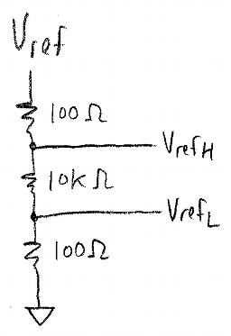
This lets us measure two voltage divider ratios, and two reference ratios. The reference ratios are so close to 0 and 1 that they are very insensitive to resistor tolerance. A 1:100:1 voltage divider that uses 1% tolerance resistors has ratios of approx 0.0098 and 0.9902, with worst-case ranges of 0.0096-0.0100 and 0.9900-0.9904. That's +/- 0.02% of fullscale accuracy out of 1% resistors! These inaccuracies are smaller than the errors caused by the gain and offset error of the MCP3201, so we can measure its inputs at 1% of fullscale (nominally 41 counts) and 99% of fullscale (nominally 4055 counts) and use the readings to compensate for gain and offset error. (We're still stuck with differential and integral nonlinearity) A high-ratio voltage divider also allows for a very low output impedance with low power dissipation (100 ohm output impedance but 10.2K fullscale resistance in the above circuit)
- Tip: Convert directly from resistor ratio to temperature
Once you've measured the ADC reading of a thermistor voltage divider, and compensated for ADC gain and offset, there are a number of ways you can convert that ADC reading to a temperature. (Remember, the relationship between voltage divider output and NTC thermistor temperature is a nonlinear operation.) Two ways not to do this are:
- lookup tables
- ADC reading -> resistance -> temperature
Lookup tables are simple. They're arrays of numbers that convert an index to an output. But they're also space hogs for the amount of accuracy you get out of them. With a 12-bit ADC, you're either going to need a 4096-element lookup table, or you're going to have to interpolate between elements of a smaller lookup table, in which case you need to do some multiplication. By the time you commit to using multiplication, you're generally better off just using a polynomial. So unless you have a lot of extra RAM or ROM (or an 8-bit ADC which only needs a 256-element lookup table) and are using a processor where hardware multiplication isn't available (no "multiply" assembly instruction), a lookup table is a poor choice for converting ADC voltage to temperature.
The other important thing to note is that while you can convert between ADC reading and thermistor resistance, and then from thermistor resistance to temperature, in almost all cases this two-step process is unnecessary and a poor choice. You don't really care what the thermistor's resistance is! You care what temperature it is. And on top of that, if you try to compute the thermistor's resistance, it varies over several orders of magnitude: it's a nearly exponential relationship with temperature, and exponentials are bad things to have to calculate with fixed-point math. (thought experiment: a Quality Z 10K thermistor at 25C will be 32.6K at 0 C, and 679 ohms at 100C. If you want 1% numerical accuracy, that means a dynamic range of 32.6K / (1% of 679 ohms) = 4800:1, which is possible in 16-bit math but doesn't leave much room in case you suddenly find out you need to sense temperature from -10 C or -20 C)
There's a general lesson here: whenever you have your choice of computations, pick the one that is the most linear possible.
What does this mean? That's another story for a future article, but briefly:
From a qualitative standpoint, take a function you have to calculate and graph it. If it looks kind of like a line, or a line with a little bit of curvature you're in good shape. If it has sharp corners or cusps or quickly turns from steep to shallow, it's going to be difficult to calculate accurately.
From a quantitative standpoint, prefer the lowest-order polynomial that approximates a computation.
In this case, if I did need to know the thermistor's resistance, I would probably express it in logarithmic terms, e.g. calculate log Rth rather than Rth itself. This is because the relationship between temperature and log Rth is closer to a quadratic or cubic polynomial, whereas between temperature and Rth is exponential.
It turns out that in most cases the relationship between voltage divider ratio α and temperature is not that nonlinear. Depending on the temperature range you care about, you may be able to get away with a 3rd-order polynomial or even a quadratic.
The approach for doing this approximation is fairly simple:
- Compute the nominal ADC voltage for a given temperature. (Alternatively: calibrate your system by measuring ADC voltage at various temperatures.)
- Use your favorite math software (MATLAB/Octave/SciLab/Mathematica/MathCAD/etc., or if you really must, use Excel) to fit a polynomial to the curve x = ADC voltage, y = temperature.
- Calculate the error between the actual temperature and the predicted temperature based on the polynomial.
- If the error is lower than your requirements, you're done; otherwise, you may need to either increase the degree of the polynomial or split the range into pieces. As a rule of thumb, polynomials of degrees higher than 5 should be avoided; the higher the polynomial degree, the more difficult it is to avoid overflow and underflow errors.
Whew!
At this point, you may be wondering, how did such a simple problem get so complicated?
Such is engineering! If it were easy, it wouldn't be interesting.


- Comments
- Write a Comment Select to add a comment
Nice, very informative article.
On polynomial approximations: In general I never like to go beyond 2nd or 3rd order either, and not just due to CPU cycles...I'll explain why in a bit. For the thermistors, third order makes a lot of sense if first order (just a line) doesn't cut it....the curve is S shaped. If it were C shaped, a second order would be my preference.
Besides computational complexity, the reason I like to avoid higher order polynomial approximations is that sooner or later I, or the next programmer might need a bit more range that what was originally intended. High order polynomials tend to quickly blow up just beyond the range they were optimized for. You see this most often when someone extrapolates from a curve fitted to empirical data.
Both the first and third order approximations will at least trend in the correct direction after you leave the mid-range area where they would be optimized. One end of the quadratic is going to head off in the opposite direction. In a control loop, that could well result in instability due to reversal of a feedback term.
Even when our processor has multiply instructions, cubing can result in overflow that needs to be dealt with. One work around is to use logarithms (hey, you, come back here...and stop that screaming!) It turns out that computing base 2 logs of binary integers is not very hard...bit shift to find the characteristic (position of leftmost 1) , and use a 16 or 32 entry lookup table to find the log of the most significant 4 or 5 bits of the mantissa.
Once you have gone through the pain of learning to do it this way, any power or root, even fractional roots become pretty trivial to compute to decent approximation.
In one of their COP400 uC application notes National Semiconductor (Remember them?) had some insight on finding base 2 logs efficiently. The COP400 assembly code is useless of course, but the algorithms are well explained:
http://www.ti.com/lit/an/snoa633/snoa633.pdf

Thanks for the detailed feedback and for the pointers to the base2 log appnote.
In general I prefer to use Cheybyshev approximation and stick with polynomials (and you are absolutely right, the choice of range is really important), but I'll have to give it a look.
Process temperature range 25°C - 90°C
Required output voltage range 0V 10V, with 25°C corresponding to 0V and 90°C corresponding to 10V
Desired non-linearity should be less than 1%
Resolution 0.5%
Ambient temperature range 0°C - 25°C
Thanks, Bob
the hyperlink you've given to the first line, is linked to the address which doesn't contain the article. http://electronics-related.com/showarticle/81.php
Instead, it must be linked to http://www.embeddedrelated.com/showarticle/81.php
Is it my circuit design is reasonable as I use Wheatstone bridge, instrumentation amplifier and low pass filter ?
and in order to linearize it, I use parallel resistor.
Great article! thanks for sharing.
Thank you for your informative article. I appreciate the time you put into this. Would you please provide the da/dT plot formulas?
I'm not sure I have them anymore; this was an early article and I didn't keep everything carefully in version control the way I do now.
Anyway, they aren't explicit formulas; the way I derived them was to fit a curve to the Quality Thermistor Z data, then consider the voltage divider function $\alpha = R_{ref} / (R_{ref} + R_{th})$ and differentiate it with respect to T: $d\alpha/dT = -R_{ref} / (R_{ref} + R_{th})^2 \times dR_{th}/dt$.
Hope this helps.
Jason -
Mad respect. Great article, thanks for sharing. I appreciate your focuses on tolerances.
I am working on a project and reading your article brought up several questions you may be willing to help with? 8 years after you posted lol.
An Arduino ATmega328P 8 bit CPU that I have coded a PID algorithm to control a radiator fan in a car depending on coolant temperature and also AC condenser split temp. It puts out a PWM signal to an OEM fan that has it's own hardware and logic, the only thing I have to do is send to the fan a 100hz at prescribed duty cycles. It works great on the bench, I'm ready for install and want to ensure a stable design in the working environment (potential for electrical noise).
4 thermistors: 10k thermistors 25°c ref for 1) ambient, 2) condenser output, and two delphi OEM thermistors for 3) radiator inlet, 4) radiator outlet.
QUESTIONS (see below for current circuit and details that may help with answers):
- What would you add to the circuit for filtering or protection?
- Would shielded cable or twisted wires help or be necessary? 24g wires okay?
- 0.10% resistors necessary?
- Why pullup vs pulldown for reference resistor? Should I change?
- Should I have a delay between my 5 data samples for a reading?
WORKING ON THE BENCH:
See bottom for pic of full circuit. I have not calibrated for absolute accuracy, but it reads as expected and the resolution sweeps great at 0.1°.
DETAILS:
- For the 10k thermistors, I use steinhart equation with spec constants, resolution coded to 0.1°c.
- For the Delphi sensors, the spec sheet only has a lookup table, so I fit steinhart best I could and is within 0.1°c through the working range.
- Time constant of fanChange->tempChange creates a PID cycle that requires temperature readings about every 5 seconds, but my display refreshes at 2Hz so that is when I get readings.
- Resolution is more important to me than absolute (but I'd like to be within 1c absolute). I just want to make sure transitions are smooth without jitter for each PID cycle at 0.1°c readings.
- Critical working temp ranges have thermistor resistance range from 1,250 ohm->130 ohm and total non-critical range starting at 50k ohm.
- Code reads the resistance using 10k pullups and converts to 0-1023.
- Code averages 5 immediate looped readings to get a value.
- I have started wiring with 24g leads from Arduino under dash to thermistors under hood, about 6 foot run and potentially passing some noisy stuff but I'm isolating best I can.
THANK YOU for any help. I'm a hobbyist so any detail you can provide with your suggestion would be helpful so I don't screw up your good advice! Any help received will certainly be passed on as anyone might ask me for help.
- Scott

You should try posting your question in the forum.
I am truly grateful for the invaluable resource provided by the tutorial titled "Thermistor Signal Conditioning: Dos and Don'ts, Tips and Tricks." This comprehensive guide offers an indispensable wealth of knowledge for anyone navigating the complexities of thermistor signal conditioning.
Thanks...
Pengrajin Mebel Jepara
To post reply to a comment, click on the 'reply' button attached to each comment. To post a new comment (not a reply to a comment) check out the 'Write a Comment' tab at the top of the comments.
Please login (on the right) if you already have an account on this platform.
Otherwise, please use this form to register (free) an join one of the largest online community for Electrical/Embedded/DSP/FPGA/ML engineers:


