


Shared-multiplier polyphase FIR filter
Keywords: FPGA, interpolating decimating FIR filter, sample rate conversion, shared multiplexed pipelined multiplier
Discussion, working code (parametrized Verilog) and Matlab reference design for a FIR polyphase resampler with arbitrary interpolation and decimation ratio, mapped to one multiplier and RAM.
Introduction
A polyphase filter can be as straightforward as multirate DSP ever gets, if it doesn't turn into a semi-deterministic, three-legged little dance between input, output and clock rates to the tune of pipeline delays.
The purpose of this article is to show how it can be done in detail, with less focus on the well-known equations but more on the practicalities.
Now, as usual, there's more than one way to skin a cat.
This (Verilog) implementation is built around a single, shared multiplier and a dual-port RAM.
The architecture is attractive when the multiplier is fast, compared to the sample rate. It makes also efficient use of dual-port RAM, which is typically available on FPGAs at no extra cost over the single-port variant.
To give a ballpark number, 100 MHz clock rate should not pose a challenge on an entry-level FPGA evaluation board such as this one (Altera Cyclone IV) or this (Xilinx Spartan 6).
That is equivalent to about 1000 MAC operations per sample of a CD audio signal, using only a small part (~5 %) of the FPGA.
While CD audio has two channels, this example implements only a single filter unit for simplicity.
It is easily extended for any number of channels or completely independent filters sharing the same multiplier and RAM, by chaining up additional states in the common state machine.
Included are a testbench with multi-rate input/output file IO and an optional top-level Matlab script that may be useful on its own as a small, self-contained design flow. The example can be run without relying on commercial tools (see links below for some selected open-source software).
Excourse: Polyphase filtering
The Verilog implementation needs only about 50 lines of code, but tells little about what it is doing, and why.
Therefore, this section gives a short review of polyphase filtering. It isn't meant to replace a textbook chapter on the topic.
"Phase" in the word "polyphase" refers to the idea that time-delayed replicas of the same signal are involved.
For example, interpolating a signal to twice the input rate creates one sample halfway between every two input samples. Those new points could be understood as a time-delayed version of the original signal (fig. 1).
Note that this explanation may serve well as intuitive explanation, but it isn't strictly accurate (it would be for the special case of a so-called "halfband filter").
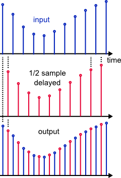
The red samples are interpolated by first interleaving zeros between the original samples (upsampling), then lowpass filtering at the resulting higher rate:

By discarding unwanted output samples, the rate can be lowered by an integer factor n (decimation, throw away n-1 out of n samples).
Thus, any conversion ratio m/n of integers can be achieved, where m is the interpolation factor and n is the decimation factor.
Efficient FIR structure
Fig. 3 shows samples in a FIR filter after interleaving zeros with the input data.
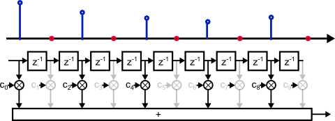
Every second multiplier does not contribute to the result, because its input sample is predictably zero.
In fig. 4, the delay line was shifted once. Now different multipliers are idle.
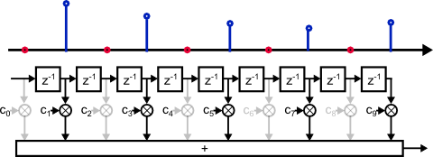
Shifting and multiplying zero samples is obviously not an efficient use of hardware resources. Neither is calculating output samples only to throw them away.
Now the same result can be obtained with less work by ordering coefficients into banks. Different output samples are obtained by switching through the coefficients.
This leads to the following structure, a textbook-style polyphase FIR resampler (fig. 7):

It is interesting to note that the computational effort is solely determined by the output rate. Neither interpolation nor decimation causes any workload by itself. For example, a five-tap filter with a conversion ratio of 999999/1000000 still needs only five multiplications per sample. However, the number of coefficients skyrockets due to the high interpolation rate (5*999999).
As a rule of thumb, polyphase filters are typically most attractive for small interpolation factors to keep the number of coefficients manageable.
Example: Coefficient sequence for 5 up 4 down resampling
(Fig. 5) illustrates the sequence of events in a 5-up 4-down resampler.
"% 5" refers to the remainder of a modulo-5 division: The bank index overflows at 5 and wraps around.
Every time this happens, the delay line is shifted and a new input sample is loaded.
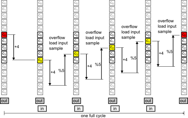
An interesting observation is that the bank index seems to run backwards. This is because steps of x and x-k are identical in modulo-k arithmetics (rewrite the latter as -(k-x)).
n > m
If the decimation factor is higher than the interpolation factor, the output rate is lower than the input rate. Occasionally, the bank index will wrap around more than once, and the delay line is shifted several times before a new output sample is loaded.
n < m
Similarly, a decimation factor smaller than the interpolation factor results in multiple subsequent output samples without delay line shift, as shown in the example.
Cycle length
For a rate-changing filter, m and n can be expected to be free of common factors, because it would make little sense to first interpolate, then immediately decimate by the same number. If so, the filter operates in cycles, and every coefficient will be used exactly once during each cycle.
In other words: Seen from the output, the length of one filter cycle through all coefficient banks equals the interpolation factor.
Note that in the example implementation, this cycle is not explicitly coded, but happens as a consequence of repeatedly adding to the bank index.
Decimation phase
A special case is to set m=n, that is, interpolate and decimate by the same number. Only a single coefficient bank will be used at a time, and it can be selected via the initial value of bankPtr (by default 0).
This structure can be used as variable delay. Functionally, it is identical to a conventional rate-1 FIR filter.
Implementation architecture
Fig. 6 shows an overview of the implementation.

It consists mainly of
- a dual-port RAM, serving double duty for storing coefficients and the input sample history
- a MAC unit to calculate and sum filter tap products
- control logic
Write port B of the RAM is unused and could be controlled externally to reconfigure the filter.
Control logic
The control block implements the indexing scheme from fig. 5. Every time the bank index wraps around, an input sample is consumed. For each output sample macCount iterates over the input history and coefficients.
Pipeline delays are compensated with delay lines that synchronize trigger commands to reset the MAC (macSet) and store its output (macRead). The higher length of the 2nd line is needed to compensate the output register of the MAC model.
The delay line concept is quite flexible, because it allows easy replacement of RAM and MAC with FPGA-specific building blocks, also to insert additional pipeline registers if needed. Otherwise, there isn't much to say. Details are documented in the code.
Maybe a single bit doesn't deserve to be called "state machine", but it is meant to be extended to support multiple channels or the like.
For most parameter settings, conditional expressions in the code become constants and the control logic simplifies greatly. While the synthesis tool will probably spot most of those, some manual cleaning might also pay off.
Other components
The download .zip file includes generic implementations for dual-port RAM and MAC.
For maximum performance they should be replaced with "megafunctions", but inference seems to work well enough at least in Altera Quartus II.
In order to keep things simple, rounding and saturation at the output are omitted. The 40+ output bit width needed for 18-bit input data still fits (barely!) into double precision floats in Matlab.
The testbench implements a simple handshaking protocol to work for arbitrary conversion rates.
The Matlab script serves as top level file, and does the following:
- compilation
- test vector generation
- calculation of reference results
- running the simulator
- comparing simulator output with the reference result
To run, invoke top in test_FIR.v. The system calls in test_FIR.m show how it is done in iverilog and command line ModelSim.
By default, the simulation creates a .vcd or .lxt2 file that can be dragged-and-dropped into gtkwave. For faster simulations, disable it by commenting out dumpvars in test_FIR.v.
Conclusion
This article describes a Verilog implementation of a polyphase FIR resampler with arbitrary interpolation- and decimation factors that multiplexes all operations to a single, pipelined multiplier. A file-streaming testbench and a Matlab reference implementation are included.
Download / links
Download design and testbench
Optional:
OctaveForge (windows)
Iverilog (windows)
GTKwave (windows)
Altera Webedition (ModelSim)


- Comments
- Write a Comment Select to add a comment
Beautiful piece of code!
Thanks for sharing.
Runs perfectly over 200MHz on spartan 6 (rewritten to vhdl :)

Links were relative to dsprelated.com, now fixed.

Thanks for sharing
To post reply to a comment, click on the 'reply' button attached to each comment. To post a new comment (not a reply to a comment) check out the 'Write a Comment' tab at the top of the comments.
Please login (on the right) if you already have an account on this platform.
Otherwise, please use this form to register (free) an join one of the largest online community for Electrical/Embedded/DSP/FPGA/ML engineers:


