


Reverse engineering wireless wall outlets
Introduction
I am improving the domotics framework that I described in a previous article:
//www.embeddedrelated.com/showarticle/605.php
I want to support wireless wall outlets, allowing me to switch devices power from a remote location over HTTP.
To do so, I could design my own wireless wall outlets and use a hardware similar to the previous one, based on the NRF905 chipset. The problem is that such a product would not be certified, and that would be an issue regarding the home insurance, in case of fire for instance. Thus, I started to look at existing certified products. My idea was to choose a product cheap and simple enough so that I could reverse engineer the wireless communication technology without modifying the product. Then, I would implement an open source software for further integration to the BANO framework.
Several wireless wall outlet products exist. I found this one:
There are 3 wall outlets by set plus a remote controller for 20 euros, which is cheap regarding other products. Also, I had the intuition that the communication technology would be simple.
Understanding the communication
First, let start with some pictures of the devices:
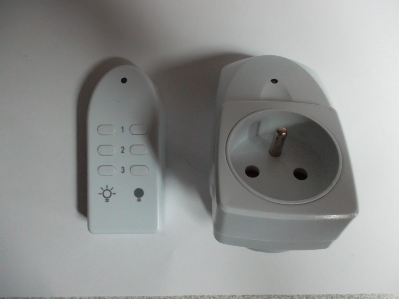
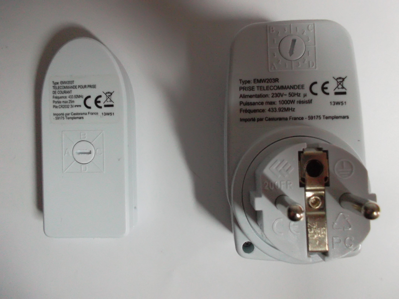
A wall outlet has a rotary key which can be set to indicate a group in A, B, C or D and a device number in 1, 2 or 3. The remote controller has 6 buttons to control outlet state. A rotary key allows to set the target outlet group. Thus, a command is uniquely identified by a triple (group, device, state). This fact will be useful when analyzing the communication protocol.
In order to get more information about the wireless technology used, I open the devices:
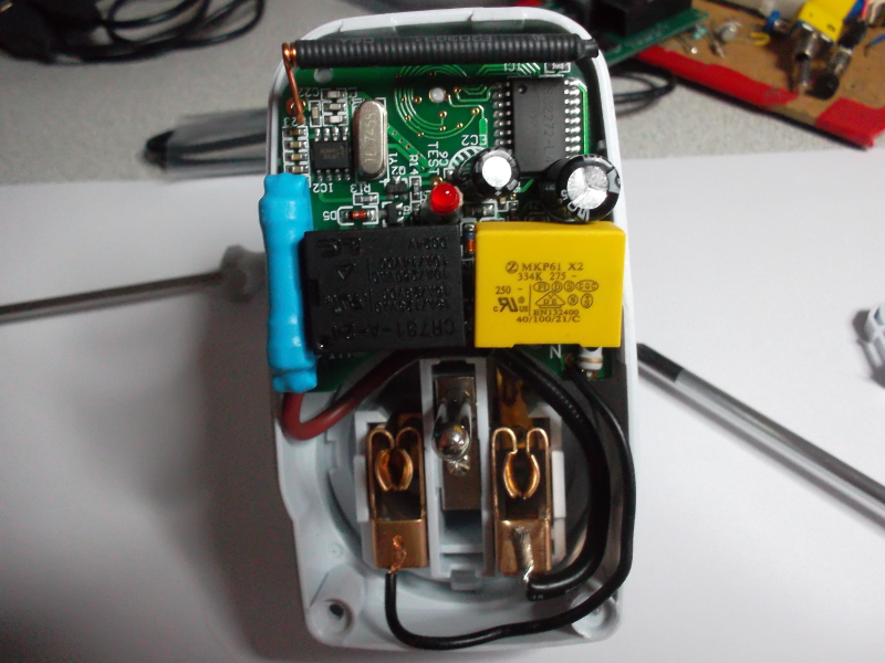
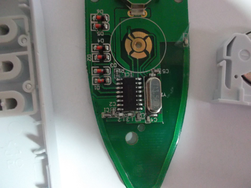
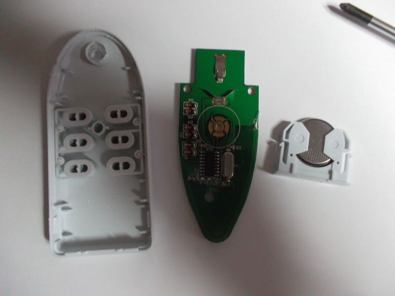
By chance, there are few components which are all clearly identifiable. It greatly helps the analysis process. Plus, it allows me to learn more about transformerless power supplies, but it is not the article purpose ... so let focus on the wireless related parts.
In the remote controller, there is a TE89TP16N MCU from HOLTEK. After some investigation, I understand that it is similar to the HT46R01T3, whose documentation is available here:
http://www.holtek.com/english/docum/consumer/4xr01t3.htm
Also, there is a RF83C IC on the wall outlet board:
http://www.hoperf.com/upload/rf/RF83.pdf
From that, I deduce that the communication is done using a 433.92 MHz OOK modulated signal. OOK stands for On Off Keying. It is the simplest case of Amplitude Shift Keying where the carrier is turned on or off to encode information:
http://en.wikipedia.org/wiki/On-off_keying
To verify this, I planed to use the same RTLSDR USB dongle that I mentioned in a previous article:
//www.embeddedrelated.com/showarticle/548.php
I am lucky enough that someone has implemented an OOK decoder that works on top of this dongle:
https://github.com/jimstudt/ook-decoder
It ships with a tool called OOKDUMP, which detects carrier pulses and dumps their duration. I ran it and used the remote control. OOKDUMP actually dumped some pulses, which confirmed the previous assumptions:
$> sudo ./ookd -v -m 0 &
$> ookdump -v
0005391.906700s ###  25 pulses
num high   low      freq
  1  500uS    856uS  -30.500kHz
  2  532uS    848uS  -28.665kHz
  3  480uS    868uS  -30.208kHz
  4 1116uS    252uS  -33.826kHz
...
I created a github repository which contains the project materials here:
https://github.com/texane/castoplug
I put a set of data captures related to this discussion in the directory:
https://github.com/texane/castoplug/tree/master/dat/ookdump
I deduce several things from the data. First, a frame is encoded using 24 pulses. There are 2 different pulses as seen by their high and low duration (approximative):
- high for 500 us, low for 900 us,
- high for 1000 us, low for 250 us.
Thus, pulses can be considered to encode bits, a frame being 3 bytes.
Second, I notice that frames do not vary for the same command, which allows us to replay frames as is.
Then, by analyzing dumps for different setups, I see that a frame is divided like this:
- the first byte encodes the group (A, B, C or D),
- the second byte encodes the device (1, 2 or 3),
- the last byte encodes the state (on or off).
From this analysis, I have everything required to do my own implementation for controlling individual wall outlets.
Reimplementing the communication
A few months ago, a friend gave me RFM22 boards which I had not yet used:
https://www.sparkfun.com/products/10153
Also, I had a spare board from a previous project featuring a 3.3V ATMEGA328P MCU, which fits perfectly to control the RFM22 over SPI. The connections are as follow:
- rfm22.nsel to atmega.pc0 (SPI CSN),
- rfm22.sck to atmega.pc1 (SPI SCK),
- rfm22.sdi to atmega.pc2 (SPI MOSI),
- rfm22.sdo to atmega.pc3 (SPI MISO),
- rfm22.snd to ground,
- rfm22.gpio_0 to rfm22.tx_ant,
- rfm22.gpio_1 to rfm22.rx_ant,
- rfm22.gpio_2 not connected.
The RFM22 board pitch is not breadboard friendly and I did some wiring. It results in the following ugly but working setup:
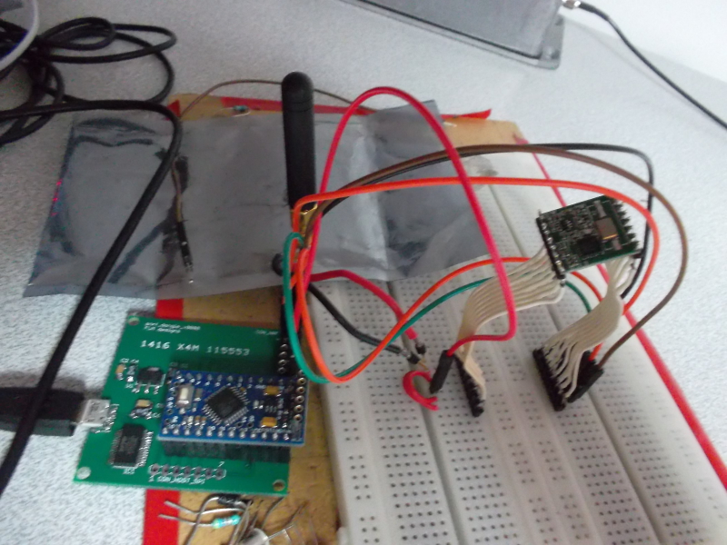
An interesting feature of the RFM22 is the so called 'direct mode', which allows to modulate the carrier wave from using a pin controlled by the MCU. It allows to precisely control the pulse durations and replay the frames seen previously. The whole implementation is contained in a single file:
https://github.com/texane/castoplug/blob/master/src/rfm22/castoplug.c
Also, an example is provided:
https://github.com/texane/castoplug/blob/master/src/rfm22/main.c
More to come
Now that I have a way to communicate with the outlets, I plan to integrate them in the BANO framework. It will require to do a RFM22 USB dongle board and some software coding ... some work but no unknowns here. Stay tuned !


- Comments
- Write a Comment Select to add a comment
To post reply to a comment, click on the 'reply' button attached to each comment. To post a new comment (not a reply to a comment) check out the 'Write a Comment' tab at the top of the comments.
Please login (on the right) if you already have an account on this platform.
Otherwise, please use this form to register (free) an join one of the largest online community for Electrical/Embedded/DSP/FPGA/ML engineers:


