




After some search on this group, at the internet and at Xilinx web
site I have not found a conclusive set of informations regarding the
behavior of a Spartan-3's input pin in a high voltage signaling.
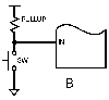
The circuit would use a 27Kohm series resistor to sense the presence
of a 24V signal. It is a very slow signal and the series limiting
resistor would use the ESD clamp diodes to keep the input voltage
below the gate oxide limits. The 27K values was chosen to have the
zero state input with maximum leakage current for this device (25uA).
I understand the 10mA limit on the clamp diodes (100mA max for this
device) would not be stressed with the near 1mA current flow but I
wonder if this situation could somehow reduce the part's MTBF and in
which amount.
I'd like to avoid using an external diode to VCCO (or a zener also
because it's knee) since any other part in the system will reduce the
overall MTBF.
In case it is important there will be 56 inputs in this condition in a
TQ144 package.

Using the help of this group I would like to include here another
question: many documents at Xilinx says the clamp diodes are not
present when the pin is configured as outputs. Is the electronic
structure of these pins with such level of complexity that can avoid
the parasitic diodes (a natural feature for a CMOS architecture)? The
XAPP429 and device's data sheet also suggest the input pin structure
for CoolRunner-II devices doesn't have clamp diode to VCCO. How can it
deal with ESD without the diode to VCCO?

Thanks in advance for your help in this matter.
-Augusto
high voltage input on SPARTAN-3 FPGAs: MTBF reduction?
Started by ●July 3, 2007
Reply by ●July 3, 20072007-07-03
AugustoEinsfeldt wrote:> After some search on this group, at the internet and at Xilinx web > site I have not found a conclusive set of informations regarding the > behavior of a Spartan-3's input pin in a high voltage signaling. > The circuit would use a 27Kohm series resistor to sense the presence > of a 24V signal. It is a very slow signal and the series limiting > resistor would use the ESD clamp diodes to keep the input voltage > below the gate oxide limits. The 27K values was chosen to have the > zero state input with maximum leakage current for this device (25uA). > I understand the 10mA limit on the clamp diodes (100mA max for this > device) would not be stressed with the near 1mA current flow but I > wonder if this situation could somehow reduce the part's MTBF and in > which amount. > I'd like to avoid using an external diode to VCCO (or a zener also > because it's knee) since any other part in the system will reduce the > overall MTBF.What about a resistor to GND ? - that will improve the noise immunity, as right now you are sensing very close to 1V, whilst 12V is better sense level for a 24V industrial type signal.> In case it is important there will be 56 inputs in this condition in a > TQ144 package.That's ~56mA of injection current - some devices have MAX limits on the alowable total injection. What else is the device doing ? Slow edges are also not great direct into a FPGA - how slow is very slow ?.> > Using the help of this group I would like to include here another > question: many documents at Xilinx says the clamp diodes are not > present when the pin is configured as outputs. Is the electronic > structure of these pins with such level of complexity that can avoid > the parasitic diodes (a natural feature for a CMOS architecture)? The > XAPP429 and device's data sheet also suggest the input pin structure > for CoolRunner-II devices doesn't have clamp diode to VCCO. How can it > deal with ESD without the diode to VCCO?The N FET avalanches, typically between 5 & 6V, and the energy is absorbed that way. -jg
Reply by ●July 3, 20072007-07-03
On Jul 2, 9:34 pm, Jim Granville <no.s...@designtools.maps.co.nz> wrote:> AugustoEinsfeldt wrote: > > After some search on this group, at the internet and at Xilinx web > > site I have not found a conclusive set of informations regarding the > > behavior of a Spartan-3's input pin in a high voltage signaling. > > The circuit would use a 27Kohm series resistor to sense the presence > > of a 24V signal. It is a very slow signal and the series limiting > > resistor would use the ESD clamp diodes to keep the input voltage > > below the gate oxide limits. The 27K values was chosen to have the > > zero state input with maximum leakage current for this device (25uA). > > I understand the 10mA limit on the clamp diodes (100mA max for this > > device) would not be stressed with the near 1mA current flow but I > > wonder if this situation could somehow reduce the part's MTBF and in > > which amount. > > I'd like to avoid using an external diode to VCCO (or a zener also > > because it's knee) since any other part in the system will reduce the > > overall MTBF. > > What about a resistor to GND ? - that will improve the noise immunity, > as right now you are sensing very close to 1V, whilst 12V is better > sense level for a 24V industrial type signal. > > > In case it is important there will be 56 inputs in this condition in a > > TQ144 package. > > That's ~56mA of injection current - some devices have MAX limits on > the alowable total injection. > What else is the device doing ? > > Slow edges are also not great direct into a FPGA - how slow is very slow ?. > > >I agree with Jim. Add a 3.3 or 3.9 kilohm transistor from each FPGA pin to ground. You get much better noise immunity and avoid all the (imaginary) diode current issues. Resistors are cheap, small, and very reliable... Peter Alfke ======================> > Using the help of this group I would like to include here another > > question: many documents at Xilinx says the clamp diodes are not > > present when the pin is configured as outputs. Is the electronic > > structure of these pins with such level of complexity that can avoid > > the parasitic diodes (a natural feature for a CMOS architecture)? The > > XAPP429 and device's data sheet also suggest the input pin structure > > for CoolRunner-II devices doesn't have clamp diode to VCCO. How can it > > deal with ESD without the diode to VCCO? > > The N FET avalanches, typically between 5 & 6V, and the energy is > absorbed that way. > > -jg
Reply by ●July 3, 20072007-07-03
Jim Granville wrote:>> In case it is important there will be 56 inputs in this condition in a >> TQ144 package. > > > That's ~56mA of injection current - some devices have MAX limits on > the alowable total injection.Another caution for this situation - is to watch the IccIO of the FPGA does not fall below ~56mA - if it does, you will need a SINKING regulator, to avoid the supply rails being pulled up - IF the VccIO pulls high, that WILL do serious things to your MTBF! :) For Source/Sinking regulators, look at DDR Termination regulators. -jg
Reply by ●July 3, 20072007-07-03
AugustoEinsfeldt <aee@terra.com.br> wrote:> After some search on this group, at the internet and at Xilinx web > site I have not found a conclusive set of informations regarding the > behavior of a Spartan-3's input pin in a high voltage signaling. > The circuit would use a 27Kohm series resistor to sense the presence > of a 24V signal. It is a very slow signal and the series limiting > resistor would use the ESD clamp diodes to keep the input voltage > below the gate oxide limits. The 27K values was chosen to have the > zero state input with maximum leakage current for this device (25uA). > I understand the 10mA limit on the clamp diodes (100mA max for this > device) would not be stressed with the near 1mA current flow but I > wonder if this situation could somehow reduce the part's MTBF and in > which amount. > I'd like to avoid using an external diode to VCCO (or a zener also > because it's knee) since any other part in the system will reduce the > overall MTBF. > In case it is important there will be 56 inputs in this condition in a > TQ144 package.Reconsider using some external buffer, with 5 Volt tolerant inputs. Those buffers have Z-Diodes to limit the voltage and will direct the current to ground. And in case anything goes wrong, it's much easier to resolder the buffer then to resolder the FPGA. If you use Schmitt Trigger Buffer, things will be saver anyways. Been there, done that. 24 Volt supply next to some logic line on a bus. Probe on the logic output. Some wrong move and: Bang: All CPLDs in the cards have that line fried by the 24 Volt applied accidently. And what's worse, the charge of PCB boards has thermal copper delamination when resoldered. Argh. By the way, does anybody know of a 5-Volt tolerant Schmitt Trigger Buffer with many inputs. The best I could find are the 2-Gate 74LVC2G14 and 74LVC2G17. Even normal Schmitt-Trigger Multigates are not to find -- Uwe Bonnes bon@elektron.ikp.physik.tu-darmstadt.de Institut fuer Kernphysik Schlossgartenstrasse 9 64289 Darmstadt --------- Tel. 06151 162516 -------- Fax. 06151 164321 ----------
Reply by ●July 3, 20072007-07-03
>Another caution for this situation - is to watch the IccIO of the FPGA >does not fall below ~56mA - if it does, you will need a SINKING >regulator, to avoid the supply rails being pulled up - IF the VccIO >pulls high, that WILL do serious things to your MTBF! :)I recall doing evil things to an Nokia 80286 machine. Shorting 5V & 12V while running did nothing. But shorting 5V to 12V killed the keyboard controller such that it failed to reboot ;)
Reply by ●July 3, 20072007-07-03
AugustoEinsfeldt <aee@terra.com.br> wrote:>After some search on this group, at the internet and at Xilinx web >site I have not found a conclusive set of informations regarding the >behavior of a Spartan-3's input pin in a high voltage signaling. >The circuit would use a 27Kohm series resistor to sense the presence >of a 24V signal. It is a very slow signal and the series limitingHow slow signal?
Reply by ●July 3, 20072007-07-03
Uwe Bonnes wrote:> By the way, does anybody know of a 5-Volt tolerant Schmitt Trigger Buffer > with many inputs. The best I could find are the 2-Gate 74LVC2G14 and > 74LVC2G17. Even normal Schmitt-Trigger Multigates are not to findThe LVC14 is 6, in SO14 and smaller DFN14 etc, but they are inverting. Then there are HC7014/HC7541 for Hex/Oct Non Inv, and HC9115, for 9 way NonInv Or devices like the Philips LVC244 (and LVC2244) have Schmitt IPs, and will do 5V IP with lower Vcc. -jg
Reply by ●July 3, 20072007-07-03
Jim Granville <no.spam@designtools.maps.co.nz> wrote:> Uwe Bonnes wrote: > > By the way, does anybody know of a 5-Volt tolerant Schmitt Trigger Buffer > > with many inputs. The best I could find are the 2-Gate 74LVC2G14 and > > 74LVC2G17. Even normal Schmitt-Trigger Multigates are not to find> The LVC14 is 6, in SO14 and smaller DFN14 etc, but they are inverting. > Then there are HC7014/HC7541 for Hex/Oct Non Inv, and HC9115, for 9 way > NonInv> Or devices like the Philips LVC244 (and LVC2244) have Schmitt IPs, and > will do 5V IP with lower Vcc.I did the mistake to only look at the TI SN74LVC244A. It neither states "hysteresis" nor "Schmitt trigger". Their Logic selction guide also only mentions "Schmitt Trigger" for the 14/17 and some similar device. The NXP datasheet mentions "Schmitt trigger" but doesn't specify a hysteresis. But at least it mentions the Schmitt trigger. At about 0.38 E for single pieces of th NXP 244A, the original poster should consider ... Thanks -- Uwe Bonnes bon@elektron.ikp.physik.tu-darmstadt.de Institut fuer Kernphysik Schlossgartenstrasse 9 64289 Darmstadt --------- Tel. 06151 162516 -------- Fax. 06151 164321 ----------
Reply by ●July 3, 20072007-07-03
On 3 Jul., 12:45, Uwe Bonnes <b...@hertz.ikp.physik.tu-darmstadt.de> wrote:> I did the mistake to only look at the TI SN74LVC244A. It neither states > "hysteresis" nor "Schmitt trigger". Their Logic selction guide also only > mentions "Schmitt Trigger" for the 14/17 and some similar device. > > The NXP datasheet mentions "Schmitt trigger" but doesn't specify a > hysteresis. But at least it mentions the Schmitt trigger.You can add hysteresis to any non inverting buffer with two resistors. Kolja Sulimma