


Hi guys!
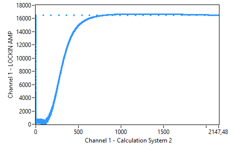
So far I've made two versions of the IIR, one is more async (IIR_Biquad_II.vhd) and one uses a state machine (IIR State). The more async one was derived from a project on the internet and it seems to work as a high pass (but gives a weird curve as low pass). I've implemented both in the FPGA and the async gives a really nice curve,
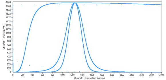
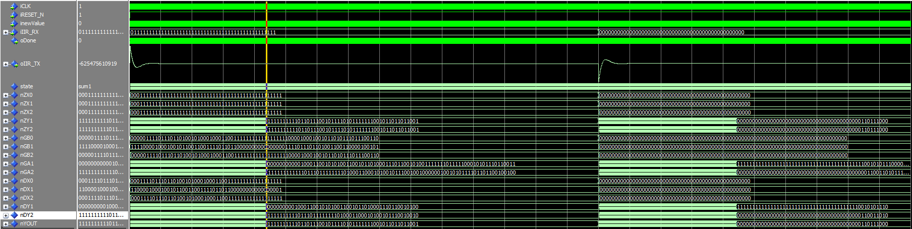
while the one with the state machine has some weird effects.
Can someone tell me why this is? I really have no clue what should cause this :-/
By the way, my own state machine implementation works fairly well as a low pass, as you can see on the picture with the two additional signals (2nd and 4th order LP).

Some general and specific thoughts, from someone who has implemented many IIR filters on FPGA:
iir_biquad version (I realize you didn't write it, but I'll make a general comment):
There's a ton of extra logic here, when all that is needed is some simple math equations and sequencing. For example line 159, etc: there is a when but no else (and no qualifier needed anyways). In general I would not recommend coding state machines and sequencing this way (the async stuff can really get you into trouble).
iirdf1 version:
I like the style much better. I like to think of the sequencing more as a pipeline problem, but a state machine works too. Not sure what your clock speed is (your extremely wide data path will affect the maximum), but generally I only need 2 clock cycles for a DF1 update. Input multiply, truncate, and usually the first sum and Z register shift can happen in the 1st cycle, then output sum calculation and output Z register shift on the 2nd cycle. If you optimize your coefficients then you can do CSD (Canonical signed digit) sums instead of using hardware multipliers, which can be helpful depending on your resource and power constraints (you generally get fewer DSP/hardware multipliers, and they can be power hungry).
As far as what's keeping this version from working, I'd say it's most likely the truncation of nDY1 and nDY2. Not exactly sure how you're intending to use QFORMAT, but usually you don't want to truncate the feedback elements.
The Q-Format determines the multiplication factor of the coefficients, so that I divide by the same factor after multiplication/summation.
The weird stuff is, that my implementation works perfectly as a low pass filter.
My clock frequency is 100MHz, my sample frequency is around 40KHz. As far as I know, I need to truncate the backwards path (or every Z register indeed) to calculate with the right values, otherwise I would multiply a 2^30 shifted coefficient with a value that was shifted 2^30 before?
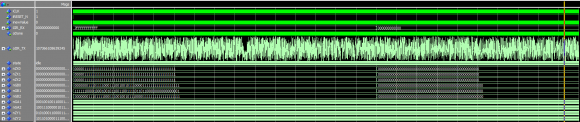
Maybe you have an example implementation for me or can edit a bit of my code? Tried to do everything in just two clock cycles, but the result is just some jitter on the output.
My input is an 48Bit signed value for everyone who's interested ^^
BTW, I really don't understand why the input in the biquad example is shifted by 12 bit to the left....
I see now why you appear to be truncating in your feedback path, that makes sense now. I did some quick edits on your file as follows:
1. If you are using numeric_std, I'd recommend not using std_logic_signed (numeric_std was designed to replace std_logic_signed/unsigned, using both is probably not good).
2. Change your numeric vector types to either signed or unsigned instead of std_logic_vector, for compatibility with numeric_std (and clarity).
3. I moved the QFORMAT normalization to immediately following the multiplication (since the intention is to reduce fractional bits out of the multiplication), instead of in the feedback path.
4. For IIR filters you will typically have significant gain in internal nodes, that needs to be reduced at the output. If you gain that down by scaling the B coefficients as you appear to have done, you take a quantization penalty (you're basically throwing away bits of your input, and if you didn't care about those bits they shouldn't be there to begin with). I'd recommending scaling your B coefficients so that B0=1.0, and scaling the output as desired in the nYOUT -> oIIR_TX equation.
5. I like using the resize() operator better than bit concatenation for lengthening signed vectors.
6. Shifting the NZY* vectors and doing the multiply on those vectors synchronously in the same cycle introduced an extra sample cycle delay in the feedback path, which made your implementation unstable.
7. Other problems I didn't fix with this code:
a) Your strobe is 1 cycle later than the data update. The inefficient way to fix this would be to just add a "done" state, but with some more thought into what math operations can be done synchronously/asynchronously and idle/sum1 you can keep the state count at 2.
b) You don't really need 3 nZX* vectors. You would have less group delay and logic if you just used 2 of them plus the unshifted input.
c) This version uses 6 hardware multipliers, which is a lot, with the benefit that the code looks fairly clean. There are many other ways to perform the multiplications, especially at your slow sample rate, which you might want to consider if you run low on hardware multipliers.
Note that internal feedback gain (ie the required vector width on feedback nodes) changes dramatically depending on the A coefficients. For this reason and others I prefer to have generic filter generation code in a higher level language (MATLAB, Python, etc) that makes very specific VHDL for a particular filter instance. DF1 is more tolerant of overflows than DF2, but overflows in particular math operations can still cause serious issues.
Wow, this is some amazing code right there :)
I wrote a small testbench for your implementation, it seems to be OK with your coefficients but after inserting mine it just gives me some jitter.
I assume this implementation is also not synthesizable because of the real format? Otherwise - damn magic :D
I didn't know the resize operation before, nice and handy tool indeed.
BTW, do you know a proper way to simulate the filter? At the moment I just give in some high jumps and watch if it reaches a certain stable value. And don't you lose on accuracy by dividing right after multiplication?
It should be synthesizable. The real format operations are all performed on constants. Every synthesis tool I've worked with recently is smart enough to perform those operations at compile time, so no FPGA logic is generated based on them.
Your coefficients produce an unstable filter because you have a pole outside the unit circle. If you keep your poles inside the unit circle (not on, but inside) then your filters will generally be stable.
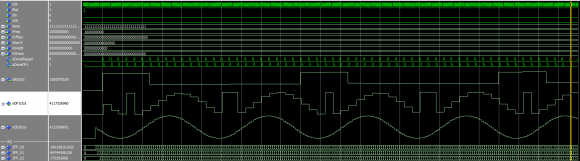
I usually simulate with sine and step input.
Example Sine input, 1kHz, amplitude 2047:
sine_wave := integer(2047.0*sin(2.0*MATH_PI*1000.0 * real(NOW/1s)));
(then convert to signed, or whatever type your input port is)
wait for SAMPLE_PERIOD; -- type time
Example step input:
step_input <= 0, 2047 after 100ns;
As for loosing accuracy, you certainly loose accuracy with each truncation, but you also save logic so there's a trade-off there. I think that where I put the truncation is reasonable, but you could always do something like preserve 2 extra fractional bits at all internal nodes (I have done that before with good results).
Ah yeah, I've swapped B0 and A0, my bad :D
The filter is totally stable in the simulation but it seems Quartus (13.1) doesn't like it, getting an Error I can't figure out.
Internal Error: Sub-system: FTM, File: /quartus/synth/ftm/ftm_arriav_atom_builder.cpp, Line: 484
Can't handle other types of sgates
Stack Trace:
0x17005c: FTM_ARRIAV_ATOM_BUILDER::map_non_wys_sgate + 0x38c
0x170458: FTM_ARRIAV_ATOM_BUILDER::build_atom_network + 0x368
0x2e295: FTM_ROOT_IMPL::build_atoms + 0x1015
0x27492: FTM_ROOT_IMPL::start_normal_flow + 0x5a2
0x26479: FTM_ROOT_IMPL::start + 0x149
0x25b78: FTM_ROOT::start + 0x128
0x60a43: scl_start + 0x5b0e3
0x615bd: scl_start + 0x5bc5d
0x656c3: scl_start + 0x5fd63
0x2e374: scl_start + 0x28a14
0x2ef1d: scl_start + 0x295bd
0x2f47f: scl_start + 0x29b1f
0x5475: scl_run_parallel_mls_script + 0xfd5
0x128ed: qexe_get_command_line + 0x206d
0x1573e: qexe_process_cmdline_arguments + 0x59e
0x15851: qexe_standard_main + 0xa1
0xa7f8: msg_exe_fini + 0x58
0xaf3c: msg_exe_fini + 0x79c
0x1f04: MEM_SEGMENT_INTERNAL::~MEM_SEGMENT_INTERNAL + 0x194
0xb8bf: msg_exe_main + 0x8f
0x8363: BaseThreadInitThunk + 0x13
0x670d0: RtlUserThreadStart + 0x20
End-trace
I'll try to compile it in a Quartus 17 project, but if it isn't synthesizable by design, quartus would have stopped earlier (stops between synthesize and fitting) and with another error I guess?
EDIT:
Needed to rewrite everything so it can be synthesized, I guess there's a problem with quartus 13.1 'cause with Quartus 17 there's no problem at all. But my sample frequency is around 40k, so some more state machine steps shouldn't be a problem. Let's hope this works well in my FPGA, the simulation (at least the jump) looks completly like your version though.
EDIT 2 : Seems like my current implementation works like the one I've posted in the start post. Looks like my damping is around -20dB for the offset and 50Hz noise. My coefficients are the same from the testbench that were calculated with Octave. With a cutoff frequency of 300Hz the curve should look like this , even better because I'm using two IIRs in serial to increase the damping even more.
So I've found the problem (I guess).
I'm just shifting the input value by 2^12 to the left, calculate everything and divide by the same value afterwards. Seems to be pretty stable and suitable for high- and lowpass stuff :)

Just make one version that works. To prove it works use a math model as your reference. Inject same input into model and design and compare outputs.
My goal is to make a universal IIR filter that fits high pass and low pass designs. As far as I know, the filter form shouldn't care about the kind of implementation, but the IIR Biquad II is derived from a solution I found on the internet (that doesn't work very well with my low pass coefficients) and the DF1 is my own interpretation of a filter in direct form 1.
IIR in FPGA are very simple computations. No need for state machine or any waits. That could cause latency issues on Y output stage.
Just use input delay line, multiple/add/truncate as per your filter.
I still suggest you use a math model to check your fpga simulation model and I am a bit unsure why you are using such massive bitwidth (48+13...or so)
I have a working Octave script that show me my filtercurve. So you say I don't need any state machine in my design? I've done another comparison and as I can see, my filter doesn't behave like the "original" one. Maybe because I'm missing some Input values I guess?


