


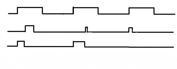
Hi,
Im currently making project of protection for voltage inverter. I know
my problem is probably too simple to even post it but im just stuck..
Anyway im using fpga because i need fast and parallel work. My problem
looks like this:
(attachment)
lets say first 2 signals are inputs and the last one is output.
Output will be exacly as first input when 2nd signal is zero.
However if 2nd signal is 1 then output turns 0, but also output signals
doesnt bring itself back to 1 until 1st signal isnt rising to 1.

I know i should use SRFF but i have problem with clock signal.. how
should it look? it should have rising edge whenever signal 1,
negated signal 1 or signal 2 is rising.
[ - ]
Reply by ●December 28, 2016

It looks like it is just a FF set by rising edge of S1 and reset by rising edge of S2. A fully synchronous design should look like;
process(clk) is begin
  if(rising_edge(clk)) then
    if(S1p&S1="01") then Output <= '1'; end if;
    if(S2p&S2="01") then Output <= '0'; end if;
    S1p <= S1;
    S2p <= S2;
  end if;
end process;
I assumed that all signals are STD_LOGIC and the clk is fast enough for your resolution.
Hope I got your problem correctly...
[ - ]
Reply by ●December 28, 2016
Problem is expressed in the form of truth table below. Note output persists at LOW after driven LOW by S2 until the next rising edge of S1 at which time S2 should NOT be HIGH.
| S2 | Y | Y |
| 1 | X | 0 |
| 0 | 0 | S1_rising |
| 0 | 1 | S1 |
Need a Flop to register Y, Need a Flop and gate to detect S1_RISE. Need a Select MUX to determine Y output.
Problem is not simple logic but Tricky logic!
[ - ]
Reply by ●December 28, 2016
Thank you very much guys, the key was to use mux, I somehow missed it, im not so great with fpga programming ;) Now its working, thanks again.


