


Three more things you need to know when transitioning from MCUs to FPGAs
I’ve had microcontrollers (MCU) in my pocket for a few decades now. They have always been much more accessible than field programmable gate arrays (FPGA) but within the last few years, that has started to change. Quite a number of companies have developed sub \$100 FPGA experimenter boards (some quite a bit sub \$100). The major vendors have low or no cost versions of their tool chains and there are a few open source options out there.
However, that increased level of accessibility doesn’t mean that you can easily jump from MCUs to FPGAs. There are a number of traps that the experienced MCU user often falls into. If you haven’t read it yet, go check out my first article on the subject, her on Embedded Related: “Jumping from MCUs to FPGAs - 5 things you need to know.” Now that you have that fresh in your mind, read on for five more things you need to know.
Item #1 - Creating multiple hardware instances, not reusing code
Code reuse in the form of functions and objects should be very familiar to anyone in the MCU world. Even modern versions of the language BASIC allow for code reuse. The concept is so fundamental that most of us do it without thinking these days.
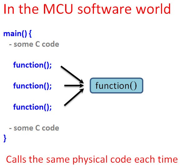
Your FPGA code can call external code code blocks, usually called modules or libraries, in the same way that your MCU code can call on external functions. In the MCU world, you are actually calling the same physical code in the same physical memory locations. The code is placed in memory once and used over and over again. Even in a more advanced system with swapping and pagefiles, the code still only takes up memory once, no matter how many times you use it. It is one of the most fundamental and earliest devised way to conserve resources in the software world.
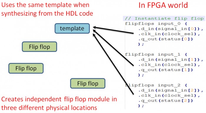
With an FPGA, however, it is not the same thing. You are conserving space in your source code file and making it more readable (I hope), but you are not conserving space inside of the FPGA. Each time you use a code module in your FPGA, you use a new section of FPGA fabric to create another piece of functional hardware. We call this instantiating a module because you are bringing a new functional part of the FPGA into being.
Conceptually, instantiating a module in an FPGA is similar to calling a function or defining an object in an MCU programming language. However, as I wrote above, in FPGA-world, you are effectively creating a separate piece of hardware. That means you need to wire it up to the rest of your hardware and you need to account for the use of FPGA logic blocks.
The use of modules and code reuse is an important part of development. However, don’t think by doing so you are conserving space in your FPGA at run time. You are not.
Item #2 - Metastability
There are many cool things you can do with an FPGA circuit. One of the coolest is that you can use different clocks in different parts of the circuits. Most decent sized FPGAs have multiple clock sources available and you can further manipulate them with counters and such so that you can go crazy with clocks.
However, like so many things that seem really cool at first, messing with multiple clocks can cause you a lot of trouble. Everything controlled by a single clock is said to be in that clock’s clock domain. If you are using more than one clock, you are using more than one clock domain. That’s fine until you need to combine logic from two or more different clock domains.
Imagine you have some logic running on a 66 MHz clock, some on a 100MHz clock and you need to perform some logic on signals from both clock domains. It’s pretty easy to see how the clock edges will at times not match up. That would be bad.
You can have the same problem even if the clocks are running at the same speed, but are from different original clocks. Say you have five logic gates or operations between clock A and your domain crossing logic, and 20 operations between clock B at your domain crossing logic. The differences in propagation delay between the two signals may put you in a situation where one samples before the other signal has stabilized. You are at risk of metastability any time that you might have a situation where the setting time from one clock might not match up properly with the sampling window.
It’s somewhat similar in concept to key bounce in the MCU world. That’s not an exact analogy, but you end up with a similar result, which is an undetermined value.
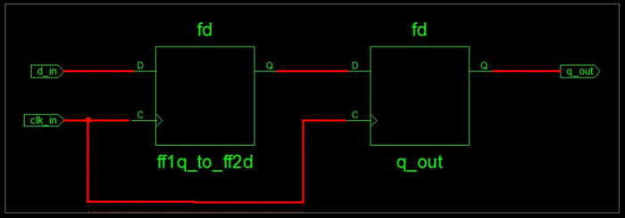
The metastability solution, however, is not a complex one. Anytime you have a signal coming in asynchronous or from a different clock domain, send it through a double flip flop, as shown above.
Clk_in is from the clock domain I’m working with in this part of the circuit. d_in is my signal from a different clock domain. The output of the first flip flop has the potential to be metastable. The output of the second flip flop will be stable.
Here is an example of code used to create the above synchronizer:
module flipflops(
    input d_in,        // The input to the first flip flop
    input clk_in,      // Clock
    output reg q_out   // The output from the second flipflop
    );

        reg ff1q_to_ff2d;    // Qout from first flip flop to Din of second

        always @ (posedge clk_in)
        begin
            ff1q_to_ff2d <= d_in;
            q_out <= ff1q_to_ff2d;
endendmodule
Item #3 - Blocking / non blocking
In FPGA land, we sometimes talk about blocking vs. non-blocking logic. The terminology was the big problem for me here. To me, those two terms conjure football imagery and I’m not much of a sports person. Fortunately, in this context, blocking has nothing to do with preventing a quarterback sack. It is better described as "immediate logic."
Non-blocking is clock-based, like a turn-based computer game. In the game, you get a bunch of stuff ready and then everyone gets to see the results at the end of the turn, but you can't get stuff ready ahead of everyone else. You can plan ahead, but everything happens in its proper turn. In non-blocking, or clock-based logic, the results of all of the logic are only accurate after the next clock cycle.
Blocking logic:
assign GATE_OUT_Y = GATE_IN_A & GATE_IN_B
Blocking: “GATE_OUT_Y” will always, immediately reflect the results of “GATE_OUT_A” AND “GATE_OUT_B.”
Non-blocking logic:
led_count <= led_count + 1;
Non-blocking: “led_count” will only be accurate after clock cycle
always @ (posedge clk)
    led_count <= led_count + 1;
    led_countB <= led_count;
    led_countC <= led_count;
end
In the above case, with each clock cycle, one line executes. First led_count increments, then we store that intermediate value in led_countB. Finally, we store the value in led_countC. For each clock cycle, one operation takes place. It takes three clock cycles for all of this to happen. They call it "non-blocking" because even though only one statement operates per clock cycle, the statement for the next clock cycle don't stop or "block" the operation of the always block.
If we uses blocking logic, something completely different happens.
always @ (posedge clk)
    led_count = led_count + 1;
    led_countB = led_count;
    led_countC = led_count;
end
All of the assignments happen at the same time. This can cause unpredictable results, depending on propagation delay and other factors. In theory, the result should end up the same as in the non-blocking example above, but it is possible for B and C to be sampled before the setting time of the increment statement leading to an undesired result.
It is best to not mix blocking and non-blocking in the same always block. And really think through what it is you are trying to do before deciding on blocking vs. non-blocking:
On to more complex projects
These three concepts, plus the five in my prior article should help you get past some of the major stumbling blocks when moving from MCUs to FPGAs. I encourage you to find yourself a development board and get started.
Duane Benson
- Comments
- Write a Comment Select to add a comment
To post reply to a comment, click on the 'reply' button attached to each comment. To post a new comment (not a reply to a comment) check out the 'Write a Comment' tab at the top of the comments.
Please login (on the right) if you already have an account on this platform.
Otherwise, please use this form to register (free) an join one of the largest online community for Electrical/Embedded/DSP/FPGA/ML engineers:


