VHDL tutorial - A practical example - part 3 - VHDL testbench
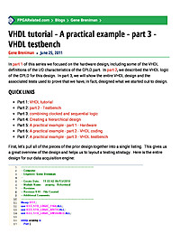
In part 1 of this series we focused on the hardware design, including some of the VHDL definitions of the I/O characteristics of the CPLD part. In part 2, we described the VHDL logic of the CPLD for this design. In part...
Summary
This blog post (part 3 of a series) walks through building a practical VHDL testbench to verify the CPLD design presented earlier. It shows how to instantiate the device under test, drive stimulus (clocks, resets, and vectors), run simulations and use assertions to automate functional checks.
Key Takeaways
- Write a structural, self-checking VHDL testbench that instantiates the DUT and drives its I/O.
- Generate and apply clock, reset, and input stimulus using processes and test vector files.
- Use assertions and report statements to create automated pass/fail checks in simulation.
- Set up and run simulator sessions (e.g., ModelSim/Altera tools) and interpret waveforms to debug behavior.
- Adapt testbench signals and timing to CPLD/FPGA I/O characteristics and constraints.
Who Should Read This
Intermediate FPGA or digital designers familiar with VHDL who want a practical, example-driven guide to building robust testbenches and running simulations for CPLD/FPGA designs.
Still RelevantIntermediate
Related Documents
- VHDL Tutorial Still RelevantIntermediate
- Architecture of FPGAs and CPLDs: A Tutorial Still RelevantIntermediate
- Performance driven FPGA design with an ASIC perspective Still RelevantAdvanced
- Free Range VHDL Still RelevantIntermediate
- How to do Math's in FPGA - Using VHDL 2008 Still RelevantIntermediate


