


Project update-2 : Digital Filter Blocks in MyHDL and their integration in pyFDA
This is an exciting update in the sense that it demonstrates a working model of one important aspect of the project: The integration or ‘glue’ between and Pyfda and MyHDL filter blocks.
So, why do we need to integrate and how do we go about it?
As discussed in earlier posts, the idea is to provide a workflow in Pyfda that automates the process of Implementing a fixpoint filter in VHDL / Verilog, and verify the correct performance in a digital design environment. MyHDL based filter-blocks package can automate both design and verification. Hence we need to integrate the two.
After discussions with my mentors, it was decided to to build an API for the filter-blocks package which would allow easy access to the filter implementations from external applications; or specifically in this case, Pyfda. It is therefore necessary to determine the ‘requirements’ or ‘filter parameters’ which need to be exchanged.
The parameters to be exchanged are listed below:
From pyfda to myhdl :
- Filter coefficients after converting from floating point to fixed point.
- Filter Stimulus (input signal).
- Fixed point word format w: (w, wi, wf). Where wi is number of integer bits, wf is the number of fractional bits and w = wi+wf+1 (additional sign bit).
From myhdl to pyfda :
- Fitler response (output signal)
It is important to note here that this list of parameters will evolve over time with further additions. Below is an example code snippet (Python) demonstrating how to pass parameters using the current iteration of the API.
Method 1 (passing parameters using a constructor):
b = [1, 2, 3, 1]  # List of numerator coefficients
a = [1]  # List of denominator coefficients
w = (24, 23, 0)  # Tuple of word format as described above
hdlfilter = FilterFIR(b, a, w) # Instantiate filter
hdlfilter.set_stimulus(np.ones(100)) # Pass numpy array for stimulus
hdlfilter.run_sim() # Run the simulation
y = hdlfilter.get_response() # Get simulation response
Method 2 (passing parameters via methods) :
b = [1, 2, 3, 1]  # List of numerator coefficients
a = [1] # List of denominator coefficients
w = (24, 23, 0) # Tuple of word format as described above
hdlfilter = FilterFIR()
hdlfilter.set_coefficients(b, a)
hdlfilter.set_word_format(w)
hdlfilter.set_stimulus(np.ones(100))
hdlfilter.run_sim()
y = hdlfilter.get_response()
Either method mentioned above can be used. This API was then used in pyfda to test the design flow. As briefly mentioned in the introductory blog post, the following flow can be used by a filter designer:
The design specifications can be entered in the ‘specs’ tab on the left panel as shown in the image below. In this case we have chosen to go with a lowpass FIR filter with pass band frequency of 0.1fs and stop band frequency of 0.3fs where fs is the sampling frequency. PyFDA then determines filter coefficients and poles/zeros from design specifications.
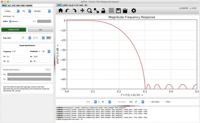
Pyfda then produces the filter response in time and frequency domain. This helps find errors in design quickly.
The generated filter coefficients based on the filter specifications can be seen in the ‘b,a’ tab as shown in the image below. The drop down in the top left corner can be used to choose between different display formats (float, dec, hex etc.). Next, the little ‘up arrow’ needs to be pressed to update all plots and widgets with the new coefficients.
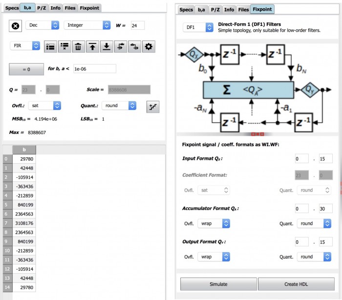
Next, in the ‘fixpoint’ tab choose the filter implementation. In this case we have chosen DF1(direct form 1). Click the ‘simulate’ button. PyFDA automatically converts filter coefficients from floating point to fixed point and passes these to the MyHDL filter blocks.
The filter response is returned to Pyfda in the form of an array which is then plotted into a graph as shown below.
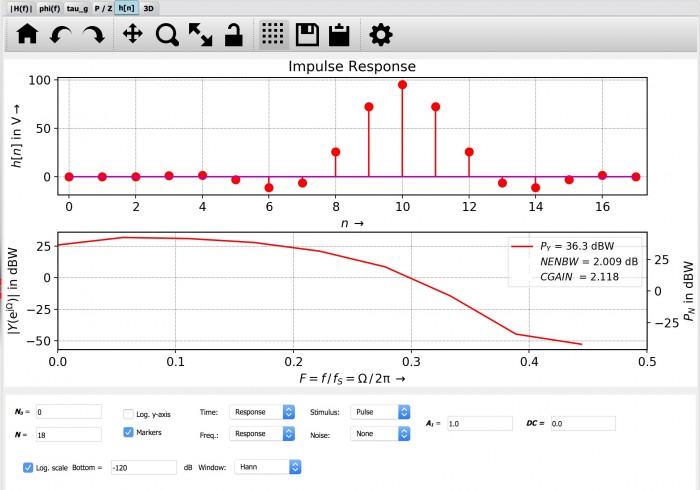
The time and frequency response is plotted in the 'h[n]' tab where one can choose between different stimuli, number of points to be plotted and other options as seen in the image above. In the case of DF1 filters, the impulse response is simply the filter coefficients.
Future additions to the API will support the generation HDL code, either VHDL or Verilog. The HDL results will match the results acquired in PyFDA.
In future blog posts, the filter-blocks API will be elaborated further and all class hierarchies, methods etc. will be discussed in detail. The aim is to create an API which which accommodates the growth of filter-blocks repository as additional filters and parameters are added.
- Comments
- Write a Comment Select to add a comment
To post reply to a comment, click on the 'reply' button attached to each comment. To post a new comment (not a reply to a comment) check out the 'Write a Comment' tab at the top of the comments.
Please login (on the right) if you already have an account on this platform.
Otherwise, please use this form to register (free) an join one of the largest online community for Electrical/Embedded/DSP/FPGA/ML engineers:


