


MyHDL ... MyPWM
The PWM topic appears to be popular lately on the fpgarelated site. This is coincidence, but I typically find the topic of modulating and demodulating signals interesting. For digital systems it is always entertaining to play with PWMs. The following PWM RTL description is quite a bit different than the PWM module described by Anton Babushkin. The module presented here is a minimal PWM engine defined at design time (i.e. not run-time).
As mentioned, the following is a basic MyHDL module to generate a PWM signal. This module is intended to be used in an FPGA. The PWM module is configured for the application at design time and compiled (synthesized, P&R) for a particular FPGA. Other than the PCM input to the PWM module there are no real-time configurations that occur. The typical use of a PWM is to configure it for the application and let it run.
To learn more about PWM signals see this overview buried in a filtering example. The following PWM module has a couple primary parameters: the system clock frequency (attribute of the clock port) and the frequency (1/period) of the output PWM (pwm_frequency). From these two parameters the number of bits will be determined. If the PWM number of bits is less than the input, the input will be truncated.
The following is a code snip that exercises the parameters and a summary given the parameters.
>>> from myhdl import *
>>> from myhdl_tools import Clock,Reset
>>> from pwm import m_pwm
>>> cfreq = (50e6,100e6,200e6,333e6,500e6)
>>> pfreq = (.5e3,1e3,10e3)
>>> Xmax,Xmin = (2**15,-2**15)
>>> reset = Reset(0, active=0, async=False)
>>> x = Signal(intbv(0, min=Xmin, max=Xmax))
>>> y = Signal(bool(0))
>>> ts = Signal(bool(0))
>>> for cf in cfreq:
        for pf in pfreq:
            clock = Clock(0, frequency=cf)
            tb_dut = m_pwm(clock,reset,x,y,ts,pwm_frequency=pf)
...
~~~[PWM Module]~~~
 clock frequency ................... 50.000 MHz
 pwm frequency ..................... 1.000 kHz
 local counter max ................. 32768
 pwm number of bits ................ 15
 pwm offset ........................ 32768
 pwm shift ......................... 1

...

~~~[PWM Module]~~~
 clock frequency ................... 500.000 MHz
 pwm frequency ..................... 10.000 kHz
 local counter max ................. 32768
 pwm number of bits ................ 15
 pwm offset ........................ 32768
 pwm shift ......................... 1

 ...
The following is the complete code for the module.
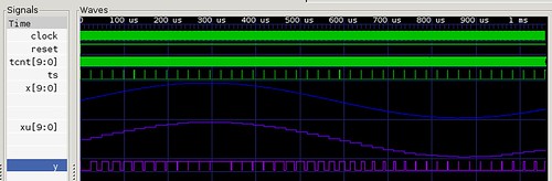
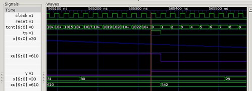
The following is a waveform from a simulation of the module. The waveform shows the input signal (x) and the output modulated signal (y).
- Comments
- Write a Comment Select to add a comment
Hi, any chance the MyHDL source for this example could be recovered, as it seems to be missing? It would make a good MyHDL learning resource, which would help me learn MyHDL as I look for useful examples.

The link in the post worked for me https://bitbucket.org/cfelton/examples/src/tip/pwm... ?
Strange, in one browser on one system I couldn't see any code at all, yet on another system I can see it plain as day. Sorry for the noise - must be something wrong with my first system.
BTW, I can't reply to you (or anyone) or DM you on MyHDL Discourse because my account is locked pending moderation for some reason - are you able to resolve this please?
To post reply to a comment, click on the 'reply' button attached to each comment. To post a new comment (not a reply to a comment) check out the 'Write a Comment' tab at the top of the comments.
Please login (on the right) if you already have an account on this platform.
Otherwise, please use this form to register (free) an join one of the largest online community for Electrical/Embedded/DSP/FPGA/ML engineers:


