Developing FPGA-DSP IP with Python
This blog post was previously titled MyHDL ASIC Proven (How is this related to FPGAs?) but the blog post has been updated and mainly discusses developing FPGA-DSP IP with Python / MyHDL. The original content is still present but the post has been reorganized and expanded. Original post 16-Mar-2010.
Developing FPGA-DSP IP with Python / MyHDL
Using Python to develop DSP logic for an FPGA is very powerful. The Python ecosystem contains many packages including numerical and scientific packages. Numpy and Scipy are two of the more popular packages available. With Numpy and Scipy signal processing design and analysis is possible in the Python language. Combining the signal processing tools and HDL into a single environment is awesome.
Many commercial products have attempts at combining these worlds but most try to bring the numeric computing to existing HDL tools (e.g. driving HDL simulation). In contrast the Python ecosystem provides a single unified environment. Python has other EDA packages including SPICE integration with eispice. The SPICE engine and HDL allow mixed-signal simulation from the Python environment.
MyHDL Introduction
MyHDL is an HDL implementation in Python and is an RTL similar to Verilog and VHDL. MyHDL adds a hardware description language to the Python ecosystem! I was first introduced to MyHDL around 2004 by a colleague from an article he had read in the Linux Journal. After some time I started actively following the project and later I made minor contributions to the project. Contributions have mainly been project postings in the project user space and some minor patches.
The goal of the MyHDL project is to empower hardware designers with the elegance and simplicity of the Python language. MyHDL is a free, open-source package using Python as a hardware description and verification language. There's a ton of information on the MyHDL website, see Why MyHDL for some of the reasons why one should consider using MyHDL. The site also has several FPGA projects and examples.
The following is a summary of some of the benefits and why one might consider MyHDL. These are excerpts from MyHDL Overview and Why MyHDL pages.
Additional reasons why:
- New to digital hardware design
- Scripting languages intensively used
- Modern software development techniques for hardware design
- Easy and quick hardware modeling (and fast)
- Algorithm development and HDL design in one enviroment
- Require both Verilog and VHDL (IP development)
- You have been TCL'd too much
- Google uses Python :)
MyHDLs First ASIC
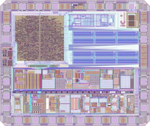
Jan Decaluwe posted information about an ASIC design where the digital portion was designed, implemented, and verified in MyHDL, see MyHDL Digital Macro for more information.

Image from www.jandecaluwe.com
The MyHDL first ASIC design is pertinent to HDL developers, FPGA and ASIC alike, because it shows the maturity of the MyHDL language / tool.
HDL DSP Example

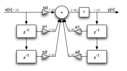
IIR Direct Form I Filter
To illustrate the power of Python / MyHDL a simple IIR filter object was created. The object, SIIR, will be used to define the IIR filter (define the response), configure the HDL, verify the HDL, and generate the synthesizable HDL.
SIIR basic usage example:
In [4]: flt = siir.SIIR(Fc=1333, Fs=48000)
IIR w,b,a 0.0555416666667
    [ 0.00676222  0.01352445  0.00676222]
    [ 1.         -1.7542798   0.78132869]
IIR fixed-point b,a
    (56726, 113451, 56726)
    (8388608, -14715966, 6554260)

In [5]: plot(flt.hz, 20*log10(abs(flt.h)))
Out[5]: []

In [10]: tb = flt.TestFreqResponse(Nloops=128, Nfft=1024)

In [11]: from myhdl import Simulation
In [12]: Simulation(tb).run()
In [13]: flt.PlotResponse()
In [14]: show()
The following is the MyHDL description for the digital hardware implementation of a second order type I IIR filter. The MyHDL version should look familiar to most digital hardware designers because MyHDL is a register transfer language (RTL). Even if the MyHDL syntax is unfamiliar the general concept is similar to Verilog and VHDL. The language has direct control of the hardware organization. MyHDL is not a higher-level synthesis tool.
@always(clk.posedge)
def rtl_iir():
    if ts:
        ffd[1].next = ffd[0]
        ffd[0].next = x

        fbd[1].next = fbd[0]
        fbd[0].next = yacc[Qd:self.Q].signed()

    # An additional clock delay but not Ts (sample rate) delay.
    y.next = yacc[Qd:self.Q].signed()

@always_comb
def rtl_acc():
    # Double precision accumulator
    yacc.next = (b0*x) + (b1*ffd[0]) + (b2*ffd[1]) - (a1*fbd[0]) - (a2*fbd[1])
The above behavioral description is a direct implementation of the difference equation for a direct form I IIR filter. In other-words, this is a straight forward hardware implementation and would require five multiplies and four additions. Nothing special has been done to optimize the hardware.
This single class allows the definition of the IIR filter (filter response) and the creation of the hardware based on the filter design. This code snippet illustrates how to use the class object for this simple IIR filter. The class object provides a means to define the filters frequency response and create the HDL. The complete source code is available on BitBucket.
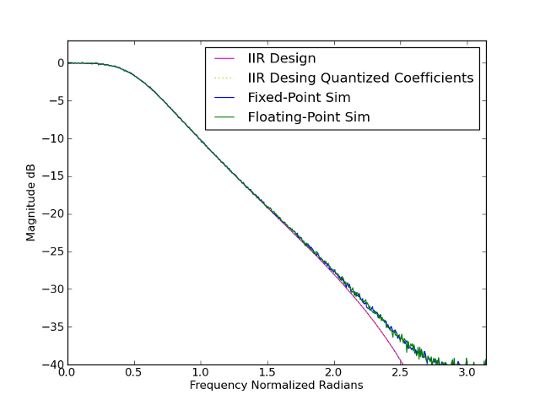
Running a simulation on the HDL IIR filter produces the Figure 3 response. This is where the power of the Python ecosystem shines. It is straight-forward to simultaneously simulate the floating-point response and the HDL response. The filter can be verified and analyzed.

IIR response and simulated response
Synthesizing the generated Verilog produces the following results for a Xilinx XC3S500E part.
As mentioned this code snippet provides an example how to use the SIIR object and the actual code is stored on BitBucket.
Conclusion
Python and MyHDL are very powerful. An FPGA-DSP design can be fully defined in a single language. Different languages and tools are not required. The Python ecosystem allows a designer to leverage a flexible language for all the steps required in developing DSP IP for an FPGA.

Power of Python
References
| [1] | www.myhdl.org |
| [2] | R. Lyons, "Understanding Digital Signal Processing", 2nd ed., Prentice Hall, Upper Saddle River, New Jersey, 2004 |
Last updated 2011-08-24
| Follow @FeltonChris |
- Comments
- Write a Comment Select to add a comment
To post reply to a comment, click on the 'reply' button attached to each comment. To post a new comment (not a reply to a comment) check out the 'Write a Comment' tab at the top of the comments.
Please login (on the right) if you already have an account on this platform.
Otherwise, please use this form to register (free) an join one of the largest online community for Electrical/Embedded/DSP/FPGA/ML engineers:


