


MyHDL FPGA Tutorial II cont. (Echo, Audio Interface)
Introduction
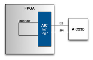
To demonstrate the echo on an FPGA board an interface to an audio ADC/DAC chip will be used. The following will explain the connection to the audio codec and the HDL module used to interface.
Audio Codec Interface
I have two boards with TI AIC23b audio codecs. The AIC23 has a configuration interface (ability to program the registers) and a streaming audio interface. The SPI mode will be used to configure the codec and the I2S interface is used to send and receive audio samples.
SPI Configuration Interface
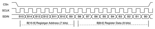
The AIC23 has a collection of registers that are used to configure / program different settings, including the sample rate, number of bits in a sample, and other settings related to the codec. The SPI has a basic method for programming the registers. The register address and data are sent via the SPI bus.
The following timing diagram illustrates the SPI transfer.
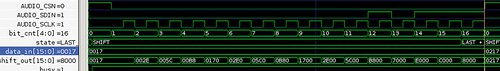
The MyHDL simulation of the SPI configuration.
I2S Audio Interface
The audio sample interface is a I2S serial connection. The I2S is a full-duplex communication path and supports left and right (stereo) samples. The I2S interface has source synchronous clock, data in, data out, and a sync signal (edges indicate beginning of sample and high / low that indicates left or right channels).
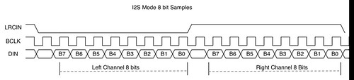
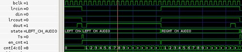
The sample bit widths can be configured to be 32, 24, and 16 bits. The audio codec only supports max 24 bits so the 32 bit setting simply sign extends the samples.
AIC Module
The HDL module used to interface to the AIC23 will drive the SPI configuration bus at start-up. It will take a static configuration, provided by the Aic23Config object, and create the register settings required. The following is an example of setting the AIC23 configuration values for the module. The module will take the settings and create the register settings.
cfgopt = Aic23Config()
cfgopt.input_len = 16
cfgopt.sample_rate = 48

# Instantiate the AIC23 interface module
g_aic23 = aic23(clock=clk96MHz,
                reset=reset,
                au_bus=au_bus,
                aic23_bus=aic23_bus,
                tst_pts=tst_pts,
                ConfigOpt=ConfigOpt)
The above code snip demonstrates how to set the configuration of the audio codec. Printing the string of the object (print(cfgopt)) will have the following output
input_len .......................... 16
right :
   hp_lock ......................... False
   mute ............................ False
   lock ............................ False
   hp_volume ....................... 121
   volume .......................... 23
   hp_zero_cross ................... True
sample_rate ........................ 48
left :
   hp_lock ......................... False
   mute ............................ False
   lock ............................ False
   hp_volume ....................... 121
   volume .......................... 23
   hp_zero_cross ................... True
The AIC module will decode the samples from the I2S bus and provide the samples via a parallel bus and a sample valid strobe (Ts). The sample valid strobe is named Ts because it will match the sample rate period. The AIC module will accept a similar input. It will take a parallel bus input, it will take the samples in at the generated Ts. The sample rate and synchronization is driven by the AIC23 codec.
To wire up a loopback is simple:
@always(clk96MHz.posedge)
def hdl_loopback():
    au_out_r.next = au_in_r
    au_out_l.next = au_in_l
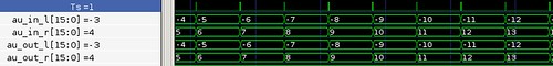
The testbench will simply increment the right channel and decrement the left channel. And the aic23_top module will loopback the audio samples. The testbench will drive the DIN port with the serial samples. The au_in_r and au_in_l will be the received samples. The samples will be looped back to the au_out_r and au_out_l. The AIC23 module will drive the DOUT port with the serial samples.
Using the AIC23 module, it will be extremely easy to use the audio interface and modify the settings, if required.
Next
So far, we have created the straight-forward hardware description to generate an echo and in this post reviewed the digital logic block used to communicate to the audio codec. In the next post the echo and the audio interface will be pulled together to demonstrate this simple echo on actual hardware. The HDL is available here.
- Comments
- Write a Comment Select to add a comment


actually i want to use this broad for my final year project, and i am tired of finding about the procedure used for audio processing.
To post reply to a comment, click on the 'reply' button attached to each comment. To post a new comment (not a reply to a comment) check out the 'Write a Comment' tab at the top of the comments.
Please login (on the right) if you already have an account on this platform.
Otherwise, please use this form to register (free) an join one of the largest online community for Electrical/Embedded/DSP/FPGA/ML engineers:


