


Altera Cyclone IV - ROM: 1-Port Problem
Hi,
I have created a MIF file containing 100 x 16bit values. The values point to a colour palette which contains the RGB values for 10 colours.
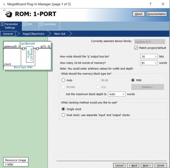
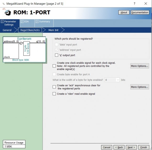
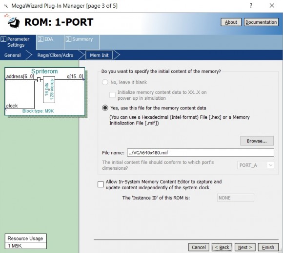
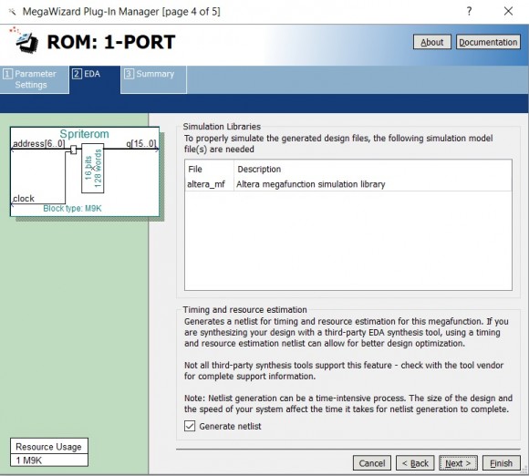
In Quartus Prime Lite I have used the IP Catalogue to create a ROM: 1-Port file
My top Verilog HDL file references the ROM file which when compiled / simulated on the FPGA development board should produce a 10 coloured stripped square (10 x 10 pixels) on the attached monitor. However, all I get is a blue square.
Could you please help me with where my code is going wrong. After I compile the design the total memory bits states 4 / 423,936 ( < 1 % ), which I believe is not right for the size of the data I am trying to place in the ROM memory.
I have attached the files for my design. Please ignore the 640x480 file name references, it should actually be 800x600
Hi.
You have a declaration in your code:
reg clock;
The width of clock here is 1. But later you use it as a counter with range 0 to 100:
clock <= clock + 1;
if(clock == 100)
clock<=0;
Also it isn’t right to use clock as clock signal for your ROM. Clk should be used instead.
Thanks for your reply.
So if I change the "clock" to "clk" how would I be able to write values to "red", "green" and "blue" (the values I am trying to write to the internal ROM, which I can then obtain the RGB values from "Pal.txt" file).
I have searched the internet for simple examples of this, but I have not, as yet, found anything that helps / I can understand.
Every registers and memory of your scheme should be clock by one signal, ‘clk’ in your case. Search for ‘synchronous design’.
To get a certain element form ROM use ‘address’, not ‘clock’
Spriterom u1(
address,
clk,
q);
do ‘address = 1’ and get ‘q’ equal 05 in the next cycle of ‘clk’
do ‘address = address +1 ’ and get ‘q’ equal 01 in the next cycle of ‘clk’
and so on.
I got 05 and 01 from your mif file.

Hello,
I don't completely understand your plan...
If you use a ROM (Read-Only Memory), why do you want to write RGB values into ROM?
As stated by Duhast, it seems that there is a mistake with the 'clock' (as well as 'address'). For correct ROM behaviour, we need a clock (it seems to be 'clk' in your code), an address signal (address in your code in order to select one value out of the 100 in the .MIF file but not yet affected) and the resulted value (q in your code).
Moreover, one thing is strange for me: in line 54, pal_memory is on 16bits but in Pal.txt, values are on 8bits; and in the .MIF, you say values are on 16bits, but the highest value is '9' (so 4bits). I don't know if it is OK for you or if there is a confusion...
Many thanks for your replies.
I have amended the code to;
`timescale 1ns / 1ps
module VGA640x480(clk, reset, red, green, blue, vsync,hsync);
input clk,reset;
output vsync,hsync;
output reg [4:0] red;
output reg [5:0] green;
output reg [4:0] blue;
reg [10:0] AH_SIZE=50;
reg axdir=1;
reg aydir=1;
//-------------------------------
// Load Spriterom from Internal
// Memory ROM: 1-Port
//-------------------------------
reg [6:0] address;
wire [15:0] q;
Spriterom u1(
address,
clk,
q);
initial address=0;
//-------------------------------
// VGA 800x600 Horizontal Values
//-------------------------------
parameter HTOTAL=1040;
parameter HZSYNC=120;
parameter HBACK_PORCH=64;
parameter HACTIVE=800;
parameter HFRONT_PORCH=56;
reg [10:0] H_SCAN;
reg HPOLARITY;
//-----------------------------
// VGA 800x600 Vertical Values
//-----------------------------
parameter VTOTAL=666;
parameter VTSYNC=6;
parameter VBACK_PORCH=23;
parameter VACTIVE=600;
parameter VFRONT_PORCH=37;
reg [10:0] V_SCAN;
reg VPOLARITY;
//-----------------------------
// Load palette
reg [15:0] pal_memory [0:29]; //16 bits wide: 3 (R G B) x 10 colours = 30
initial $readmemh("Pal.txt", pal_memory);
//-----------------------------
// Horizontal Timings
//-----------------------------
always@(posedge clk)
begin
//Horizontal Sync
if(H_SCAN < HZSYNC)
HPOLARITY <= 0;
else
HPOLARITY <= 1;
//End of line
if(H_SCAN == HTOTAL)
H_SCAN <= 0;
else
H_SCAN <= H_SCAN + 1'b1;
end
assign hsync = HPOLARITY;
//-----------------------------
// Vertical Timings
//-----------------------------
always@(posedge clk)
begin
//Vertical Sync
if(V_SCAN < VTSYNC)
VPOLARITY <= 0;
else
VPOLARITY <= 1;
//Bottom of screen
if(H_SCAN == HZSYNC + HBACK_PORCH + HACTIVE)
if(V_SCAN == VTOTAL)
V_SCAN <= 0;
else
V_SCAN <= V_SCAN + 1;
end
assign vsync = VPOLARITY;
always@(posedge clk)
begin
if((H_SCAN > HZSYNC+HBACK_PORCH) && (V_SCAN > VTSYNC+VBACK_PORCH) && (H_SCAN < HZSYNC+HBACK_PORCH+HACTIVE+1) && (V_SCAN < VTSYNC+VBACK_PORCH+VACTIVE+1))
begin
if((H_SCAN > HZSYNC+HBACK_PORCH+100) && (V_SCAN > VTSYNC+VBACK_PORCH+50) && (H_SCAN < HZSYNC+HBACK_PORCH+110+1) && (V_SCAN < VTSYNC+VBACK_PORCH+60+1))
begin
red <= pal_memory[q*3]>>3;
green <= pal_memory[(q*3)+1]>>2;
blue <= pal_memory[(q*3)+2]>>3;
address <= address + 1;
if(address == 100)
address<=0;
end
else
if((H_SCAN > HZSYNC+HBACK_PORCH+100) && (V_SCAN > VTSYNC+VBACK_PORCH+70) && (H_SCAN < HZSYNC+HBACK_PORCH+110+1) && (V_SCAN < VTSYNC+VBACK_PORCH+80+1))
begin
red <= 0;
green <= 255>>2;
blue <= 0;
end
else
begin
red <= 0;
green <= 0;
blue <= 0;
end
end
else
begin
red <= 0;
green <= 0;
blue <= 0;
end
end
endmodule
This draws a coloured square on the VGA monitor but the image is rolling to the right quite quickly (within the 10x10 pixel area). I have also added a green square below this as a comparison (both squares are the same size). The rolling square appears to only have 3 or 4 colours.
I have initially set address = 0, as the first value is at address 0 (0 to 99).
I'm not trying to write to the ROM, the red, green and blue are connected to the VGA on my development board (sorry, I didn't make this clear). For simplicity I have only included 8 bit values in Pal.txt. My intention is to use a larger palette, up to 255 colours.
Your help again to try and get this right would be very much appreciated.
Are you sure about your video synchros???
I mean that H_SCAN counts from 0 to HTOTAL so 'HTOTAL+1' (1041) clock cycles. I suggest that you replace 'if(H_SCAN == HTOTAL)' by 'if(H_SCAN == HTOTAL-1)'; so that your signal counts from 0 to 1039 (1040 clock cycles). Same for V_SCAN.
-> You should have a stable video now...
If I understand clearly your code, a 10x10 area will be displayed starting at pixel (100; 50) to pixel (109; 59) with the contents of the .MIF and Pal.txt files. Do you want this behaviour?
Identically, address counts from 0 to 100 (101 clock cycles). So each time a frame will be completed, you will have a shift of one pixel in your 10x10 square.
Thanks for the reply
I have amended the code to;
`timescale 1ns / 1ps
module VGA640x480(clk, reset, red, green, blue, vsync,hsync);
input clk,reset;
output vsync,hsync;
output reg [4:0] red;
output reg [5:0] green;
output reg [4:0] blue;
reg [10:0] AH_SIZE=50;
reg axdir=1;
reg aydir=1;

//-------------------------------
// Load Spriterom from Internal
// Memory ROM: 1-Port
//-------------------------------
reg [6:0] address;
wire [15:0] q;
Spriterom u1(
 address,
 clk,
 q);
initial address=0;

//-------------------------------
// VGA 800x600 Horizontal Values
//-------------------------------
parameter HTOTAL=1040;
parameter HZSYNC=120;
parameter HBACK_PORCH=64;
parameter HACTIVE=800;
parameter HFRONT_PORCH=56;
reg [10:0] H_SCAN;
reg HPOLARITY;
//-----------------------------
// VGA 800x600 Vertical Values
//-----------------------------
parameter VTOTAL=666;
parameter VTSYNC=6;
parameter VBACK_PORCH=23;
parameter VACTIVE=600;
parameter VFRONT_PORCH=37;
reg [10:0] V_SCAN;
reg VPOLARITY;
//-----------------------------
// Load palette
reg [15:0] pal_memory [0:29]; //16 bits wide: 3 (R G B) x 10 colours = 30
initial $readmemh("Pal.txt", pal_memory);
//-----------------------------
// Horizontal Timings
//-----------------------------
always@(posedge clk)
begin
 //Horizontal Sync
 if(H_SCAN < HZSYNC)
  HPOLARITY <= 0;
 else
  HPOLARITY <= 1;

 //End of line
 if(H_SCAN == HTOTAL-1)
  H_SCAN <= 0;
 else
  H_SCAN <= H_SCAN + 1'b1;
end
assign hsync = HPOLARITY;
//-----------------------------
// Vertical Timings
//-----------------------------
always@(posedge clk)
begin
 //Vertical Sync
    if(V_SCAN < VTSYNC)
  VPOLARITY <= 0;
 else
  VPOLARITY <= 1;
 //Bottom of screen
    if(H_SCAN == HZSYNC + HBACK_PORCH + HACTIVE-1)
  if(V_SCAN == VTOTAL-1)
   V_SCAN <= 0;
 else
  V_SCAN <= V_SCAN + 1;
end
assign vsync = VPOLARITY;

always@(posedge clk)
begin
 if((H_SCAN > HZSYNC+HBACK_PORCH-1) && (V_SCAN > VTSYNC+VBACK_PORCH-1) && (H_SCAN < HZSYNC+HBACK_PORCH+HACTIVE) && (V_SCAN < VTSYNC+VBACK_PORCH+VACTIVE))
  begin
   if((H_SCAN > HZSYNC+HBACK_PORCH-1+100) && (V_SCAN > VTSYNC+VBACK_PORCH-1+50) && (H_SCAN < HZSYNC+HBACK_PORCH+110) && (V_SCAN < VTSYNC+VBACK_PORCH+60))
    begin
     red <= pal_memory[q*3]>>3;
     green <= pal_memory[(q*3)+1]>>2;
     blue <= pal_memory[(q*3)+2]>>3;
     address <= address + 1;
     if(address == 99)
      address<=0;
    end

   else
    begin
     red <= 0;
     green <= 0;
     blue <= 0;
    end
  end
else
  begin
   red <= 0;
   green <= 0;
   blue <= 0;
  end
end
endmodule
I have made the changes you suggested. I have also noticed that;
if((H_SCAN > HZSYNC+HBACK_PORCH) && (V_SCAN > VTSYNC+VBACK_PORCH) && (H_SCAN < HZSYNC+HBACK_PORCH+HACTIVE+1) && (V_SCAN < VTSYNC+VBACK_PORCH+VACTIVE+1))
  begin
   if((H_SCAN > HZSYNC+HBACK_PORCH+100) && (V_SCAN > VTSYNC+VBACK_PORCH+50) && (H_SCAN < HZSYNC+HBACK_PORCH+110+1) && (V_SCAN < VTSYNC+VBACK_PORCH+60+1))
appeared to be wrong. Perhaps you could please advise (or otherwise) if you agree to these changes.
I have changed: if(address == 100) to 99.
The image displays steady on the monitor but I am missing the 10th pixel on each horizontal line (i.e. 9 wide x 10 high).
If I understand clearly your code, a 10x10 area will be displayed starting at pixel (100; 50) to pixel (109; 59) with the contents of the .MIF and Pal.txt files. Do you want this behaviour?
The .mif file contains different values (eg. 01) and the "Pal.txt" file contains 30 values (consecutive values for Red Green Blue x 10). This is how the colour of each pixel is displayed. I shift right Red and Blue by 3 bits and Green by 2 bits, to match the RGB available bits on the development board. Is there a better way to do this or have I misunderstood your question?
My question was to be sure my understanding... You would like to display on the monitor a 800x600 black and steady image; like this:
____________
| |
| XX |
| XX |
| |
____________
where XX represents a 10x10 area (so the 100 values into .MIF; one value into the .MIF represents a colour which is RGB'ed thanks to Pal.txt file). The 10x10 area is positionned at pixel (100; 50) to pixel (109; 59).
Why do you think your code is wrong?
if ((H_SCAN > HZSYNC+HBACK_PORCH) && (V_SCAN > VTSYNC+VBACK_PORCH) && (H_SCAN < HZSYNC+HBACK_PORCH+HACTIVE+1) && (V_SCAN < VTSYNC+VBACK_PORCH+VACTIVE+1))
  begin
   if((H_SCAN > HZSYNC+HBACK_PORCH-1+100) && (V_SCAN > VTSYNC+VBACK_PORCH-1+50) && (H_SCAN < HZSYNC+HBACK_PORCH+110) && (V_SCAN < VTSYNC+VBACK_PORCH+60))
By replacing with the value, it comes:
if ((H_SCAN > 184) && (V_SCAN > 29) && (H_SCAN < 985) && (V_SCAN < 630))
begin
    if((H_SCAN > 283) && (V_SCAN > 78) && (H_SCAN < 294) && (V_SCAN < 89))
So the second 'if' will entered if H_SCAN and V_SCAN will respectively be in the range [284; 293] (10 values) and [79; 88] (10 values).
So, for me, it's correct...
Why do you miss the 10th pixel?
Good question! Difficult to say without deeper knowledge of the whole system...
As you are in RGB, you do not have to worry about chroma subsampling...
Can you test with a 8x8 area (or 8x10) and a 9x9 area (or 9x10)?
Is it better? Or do you still have the last column missing?
With the values that you have entered, I can see that the code is correct, thanks for that.
I have created the different combinations which you have suggested and each time the right most pixel on each line is missing.
Example: for 9x9 (a square with a border around using palette codes 01 and 02;
01 01 01 01 01 01 01 01 01
01 02 02 02 02 02 02 02 01
01 02 02 02 02 02 02 02 01
01 02 02 02 02 02 02 02 01
01 02 02 02 02 02 02 02 01
01 02 02 02 02 02 02 02 01
01 02 02 02 02 02 02 02 01
01 02 02 02 02 02 02 02 01
01 01 01 01 01 01 01 01 01
I'm not entirely sure if I have created the ROM file correctly using the Megawizard in Quartus Prime Lite. I have attached a screen shot of the 5 stages to create it.
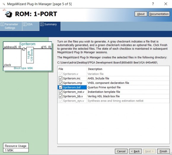
ROM generation seems to be OK.
One way to resolve the problem is to get rid of (temporarily) the ROM and affect constant values to red/green/blue.
red <= 255; //instead of red <= pal_memory[q*3]>>3;)
green <= 255; //instead of green <= pal_memory[(q*<span class="hljs-number">3</span>)+<span class="hljs-number">1</span>]>><span class="hljs-number">2</span>;
blue <= 255; //instead of blue <= pal_memory[(q*<span class="hljs-number">3</span>)+<span class="hljs-number">2</span>]>><span class="hljs-number">3</span>;
Then, as I said, you may try with different square areas. Using constants may be easier:
if((H_SCAN > HZSYNC+HBACK_PORCH) && (V_SCAN > VTSYNC+VBACK_PORCH) && (H_SCAN < HZSYNC+HBACK_PORCH+HACTIVE+1) && (V_SCAN < VTSYNC+VBACK_PORCH+VACTIVE+1))
  begin
   if((H_SCAN > HZSYNC+HBACK_PORCH+ORIGIN_X) && (V_SCAN > VTSYNC+VBACK_PORCH+ORIGIN_Y) && (H_SCAN < HZSYNC+HBACK_PORCH+ORIGIN_X+SIZE_X+1) && (V_SCAN < VTSYNC+VBACK_PORCH+ORIGIN_Y+SIZE_Y+1))<span class="redactor-invisible-space"></span>
where (ORIGIN_X; ORIGIN_Y) is the origin (top left corner: (100; 50) in your original code) and (Size_X; Size_Y) is the size of the square ((10;10) in your original code).
You may try especially 1x1 area (or 1x10 area). Is it OK?
Maybe, chroma subsampling is the problem (but I don't think..). Try with an odd ORIGIN_X (ORIGIN_X=101 for example). Is it OK?
1. I tried an image 2x10 and lost the 2nd (last) pixel, as in previous attempts (this was still using the read from ROM values): ROM contained "01 02 01 02 01 02 01 02 01 02 01 02 01 02 01 02 01 02 01 02" and I changed my colour palette to "ROM Data 01 = FF FF 00 = Yellow" and "02 = 00 00 FF = Blue"
2. I tried an image 1x10 and nothing appeared on the screen.
3. Then, as you suggested I used RGB values (255,255,0) for an image 1x10 and I could see the yellow 10 pixel vertical line, however, this was half the thickness (width) compared to number 1 above. It looks like item 1 above is showing 2 pixels wide but in yellow, not yellow + blue as I would have expected.
Just a thought, I have something in my mind that I think I read somewhere that the clock speed for reading ROM/RAM should be twice the speed of the normal clock speed (i.e 100Mhz clk for ROM read and 50Mhz clk speed for everything else). But I may be getting confused with something else.
I have since done the following;
1. Installed the latest update for Intel Quartus Prime Lite 18.1.1
2. Created new a MIF file 9x9 pixels using 8 bit values
+0 +1 +2 +3 +4 +5 +6 +7 +8
00: 01 01 01 01 01 01 01 01 01
09: 01 02 02 02 02 02 02 02 01
18: 01 02 02 02 02 02 02 02 01
27: 01 02 02 02 02 02 02 02 01
36: 01 02 02 02 02 02 02 02 01
45: 01 02 02 02 02 02 02 02 01
54: 01 02 02 02 02 02 02 02 01
63: 01 02 02 02 02 02 02 02 01
72: 01 01 01 01 01 01 01 01 01
3. Created a new Spriterom file using Quartus Prime Megawizard with 8 bit values
4. Pal.txt only contains four colours
00: FF 00 00 = Red
01: FF FF 00 = Yellow
02: 00 00 FF = Blue
03: FF FF FF = White
5. Checked the 800x600 @ 72hz timings
Arranged the Horizontal and Vertical in this order;
HACTIVE + HFRONT_PORCH + HZSYNC + HBACK_PORCH
800 + 56 + 120 + 64
VACTIVE + VFRONT_PORCH + VTSYNC + VBACK_PORCH
600 + 37 + 6 + 23
Changed line 100 in my top module to:
if(H_SCAN == HTOTAL-1) // was: HZSYNC + HBACK_PORCH + HACTIVE-1)
When the 9x9 image is not being drawn, i have set all other pixels in the active 800x600 range to red.
FINDINGS;
The last horizontal pixel in the 9x9 image is actualy being displayed as black pixels. This was the reason why i could not see it with all other pixels (besides the 9x9 image) being black also.
So, the last pixel in each horizontal line of the image is always showing in black.
If anyone has any suggestions, that would be very nuch appreciated.
I have tried (but with little success) created a test bench with ModelSim-Altera and ran the RTL simulation through NativeLink. If anyone could help with this, it would also be very much appreciated.
To help, I have attached 5 files in respect of the above;
You don't need to have a two times faster clock. In your case, you would like to generate one pixel at each clock cycle, and so we need to read one value out of ROM each clock cycle.
You may need to have a faster clock if you store into the ROM the 3 values of the pixel. In this case, you will need to read one red then one green and finally one blue at a clock 3 times faster than glue logic.
I don't catch what your problem is now...
I suggest that you use a SignalTap to see what happens in your design. The code seems to be OK but a view of the real behaviour on board will be usefull...
Many thanks for the reply and for explaining about when to use faster clock speeds, it makes sense now.
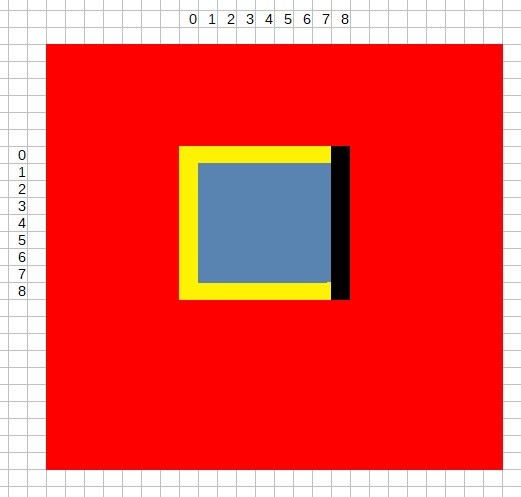
I have shown below what the screen looks like (not an actual screen shot though).
It should be a red background (which it is) and the 9x9 image should have a yellow border with inner pixels blue. However, the last pixel on each horizontal line of the 9x9 image is always black, regardless of the value I use in the MIF / ROM file. The Pal.txt file does not have a colour palette for black set.
Hope this makes sense and you understand the problem.
I have tried the Signal Tap Logic Analyser. I set the signal configuration: clock to "clk" and tried different combinations of nodes "q" , "address" , "H_SCAN" and "V_SCAN", but I cant' seem to see any changes in "q". I have also tried different levels of sample depth. I have selected "Start Compilation", "Program Device" and "Run Analysis"
I also tried using the "clock" from the Spriterom module as the signal configuration: clock.
Guess what I am trying to obtain is the 81 values of "q" for the 9x9 image. Could you please give me some pointers on how to set this up?
Your assistance is very much appreciated.
The last column in black is interesting as it seems to be not authorized in your code (not red, not yellow neither blue). Thus it seems that your code is correct... Let's check using SignalTap!
Config:
Keep clk for clock. Put 1k for sample depth.
Setup tab:
Select the signals you wish to see and/or trigger (H_SCAN, V_SCAN, address, q, red, green, blue)
Set the trigger: H_SCAN = HZSYNC+HBACK_PORCH+ORIGIN_X+1 = 284 (you need to check!) and V_SCAN = VTSYNC+VBACK_PORCH+ORIGIN_Y+1 = 79 (check!)
-> Compile, program, run analysis
SignalTap will display 1024 clock cycles (the 1k you put in sample depth) from the trigger...
ie when H_SCAN will be 284 and V_SCAN will be 79, it will display H_SCAN, V_SCAN, address, q, red, green, blue.
You can check if it is correct as expected... (for 284 and 79, you are (normally) in the top left corner of your NxN area, so you should have address=0 and a q corresponding to the first elemet in your .MIF, so a red/green/blue at yellow).
Check with different valeus of triggers (different values of H_SCAN and V_SCAN) to see if all RGB are correct... (you don't need to re-compile when changing trigger values. Recompiling is just needed if we add new signal or config).
Thanks for getting back again.
I have re-arranged my horizontal and vertical layout as shown in this file VGA640x480.v
The 9x9 image should be displayed at 100,50 (64h,32h)
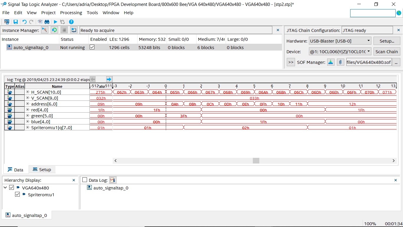
I have hopefully run SignalTap as you described as follows;
Setup: Pic 1.jpg
At 100,50 (64h,32h): Pic 2.jpg
At 100,51 (64h,33h): Pic 3.jpg
If I am reading the data correctly things do not seem to line up;
at 100,50: address=0, RGB=Red (Not Correct)
at 108,50: address=8, RGB=Yellow (Correct)
at 100,51: address=9, RGB=Red (Not Correct)
at 108,51: address=17 (11h), RGB=Blue (Nor Correct)
First of all, there is one clock cycle between the 'input' and the 'output' of your process. So at (100; 50), you compute the pixel which will be available at the next clock cycle. So, here you have RGB=(1F; 3F; 0) for that pixel (100; 50).
For the 50th row, you have 9 pixels at yellow.
For the 51th row, you have 2 pixels at yellow, followed by 7 pixels at blue.
I have commented one of your image: pic 2_22402.jpg
One problem of your code is that the 'q' value will be late by one clock. So, I think that you need to anticipate and start counting at -1 (initial address=-1).
I suggest that you modify your ROM with different values (@0=1, @1=2, ...). In that way, you will see the corresponding value of q according to the address (which will be one clock earlier). For pixel (100;50), you need to have the corresponding q and an address at 1 (because you should anticipate the value q needed for pixel (101;50) ).
Hope this is clear!
I also suggest that you put Red, Green and Blue signals in 'Trigger Enable'. In that way, by triggering Red=Green=Blue=0, you could see for which pixel you have black value. According to your code, it should appear in the synchro portion. But as you stated earlier, you have black in video portion (maybe you should change the value in the synchro to not have black).
I have set address=-1, changed the ROM file to values 01 02 03 04 05 06 07 08 09 and changed my Pal.txt to include the 01 to 09 RGB colours (FF 00 00 FF FF 00 00 00 FF FF FF 00 00 00 FF FF FF 00 00 00 FF FF FF 00 00 00 FF FF FF 00 00 00 FF FF FF FF)
Prior to my "IF" is true for 100,50 "q" contains 01h even though the value of "address=-1". Is this because a negative value in "address" will result in fetching from ROM the 1st value, in this case 01h.
H_SCAN and V_SCAN are being checked and incremented accordingly on each positve "clk" pulse, and it is not until the following positive "clk" pulse when any new values of H_SCAN and V_SCAN are available in my "Display Image on VGA Monitor" design
Whem my "IF" is true for 100,50 (one clock pulse on from when H_SCAN and V_SCAN equalled these values) "q" still contains 01h, R G B = 1F,3F,00, address starts at "-1" and is incremented to "0".
The next clk pulse, as "address=0", "q" will again have a value of 01h
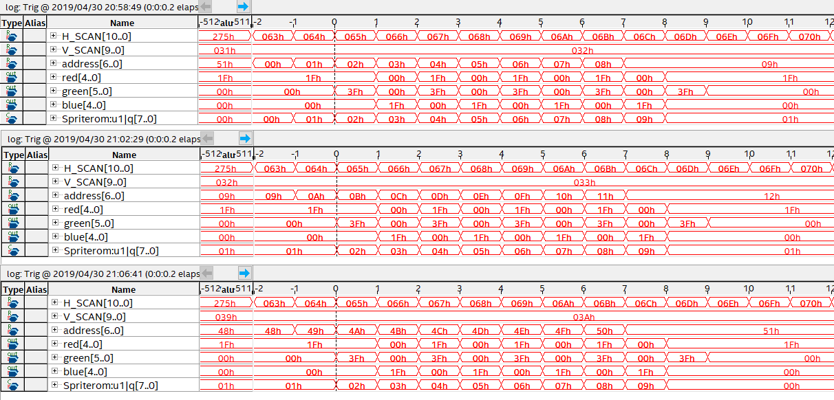
I understand why you suggest to initially set address=-1 as this aligns the values in SignalTap. However, this has an effect on "q". "q" has the same value for H_SCAN=100 and 101, as shown in this data from SignalTap; address -1.png
I have tried to align "q" by including;
if(address == 0)
address <= address + 1;
here;
if((H_SCAN >99) && (V_SCAN > 49) && (H_SCAN < 109) && (V_SCAN < 59))
begin
red <= pal_memory[q*3]>>3;
green <= pal_memory[(q*3)+1]>>2;
blue <= pal_memory[(q*3)+2]>>3;
address <= address + 1;
if(address == 0)
address <= address + 1;
else if(address == 80)
address<=0;
end
but this has no effect on the values in "q".
I tried triggering Red, Green and Blue = 0 and did not see them in the 9x9 image area (that's if I did it right).
Also changed the Red, Green and Blue values = 1 for the syncro, this didn't appear to change anything.
I confess that I don't understand everything...
Secondly, as Verilog is not my prefer language (I am more a VHDL expert!), maybe the "address=-1" is not correct in verilog.
One way to resolve your address mismatch is to anticipare with a second 'IF'.
if((H_SCAN==98) && (V_SCAN==50))
begin
  // Initialisation at pixel (98; 50)
  //   -> address should be 0 when (99; 50)
  //   -> so when (100; 50) data (present at @0) will be available for the
  // computation of the pixel
address <= 0;
end
if((H_SCAN>98) && (V_SCAN > 49) && (H_SCAN < 108) && (V_SCAN < 59))
begin
  // count for pixel (99; 50) ... (107; 50)
  // ...
  // count for pixel (99; 58) ... (107; 58)
  // when (106; 58), address whould be 80 decimal
  // when (107; 58), address whould be 81 decimal
  address <= address + 1;
end
if((H_SCAN >99) && (V_SCAN > 49) & && (H_SCAN < 109) && (V_SCAN < 59))
begin
  red <= pal_memory[q*3]>>3;
  green <= pal_memory[(q*3)+1]>>2;
  blue <= pal_memory[(q*3)+2]>>3;
end
You should have something like this:
H_SCAN  98 99 100 101 102 103 104 105 106 107 108 109 ...
V_SCAN  50 50 50  50  50  50  50  50  50  50  50  50  50
address X  0  1   2   3   4   5   6   7   8   9   9   9    -> X should be 81 (rollover)
q[7:0]  X  X  1   2   3   4   5   6   7   8   9  10  10    -> X should be 82(rollover)
              <-------------------------------->
              9 required values from (100;50) to (108; 50)

H_SCAN  98 99 100 101 102 103 104 105 106 107 108 109 ...
V_SCAN  51 51 51  51  51  51  51  51  51  51  51  51  51
address 9  9  10  11  12  13  14  15  16  17  18  18  18
q[7:0]  10 10 10  11  12  13  14  15  16  17  18  19  19
              <-------------------------------->
              9 required values from (100;51) to (108; 51)

...

H_SCAN  98 99 100 101 102 103 104 105 106 107 108 109 ...
V_SCAN  58 58 58  58  58  58  58  58  58  58  58  58  58
address 72 72 73  74  75  76  77  78  79  80  81  81  81
q[7:0]  73 73 73  74  75  76  77  78  79  80  81  82  82
              <-------------------------------->
              9 required values from (100;58) to (108; 58)
>>I tried triggering Red, Green and Blue = 0 and did not see them in the 9x9 image area (that's if I did it right).
So, you didn't see black column in the 9x9 area while there is this column in the display.
>>Also changed the Red, Green and Blue values = 1 for the syncro, this didn't appear to change anything.
This was just to be sure that when you set your trigger to RGB=0, we didn't capture during synchro.
I suggest that you continue so as to be sure the 9x9 area is correct (thanks to SignalTap). When this will be correct, you can investigate further...
What is your connection after FPGA: Are RGB signals connected directly to monitor or is there is video encoder?
Your code seems to be working very well: Alligned.png
I tried the original 9x9 yellow border filled with blue and it worked very well. I have tried a larger image (clipart off Google) with more colours and this also works very well;

Although the camera on my phone used to take the screen shot is not the best. The left image (a bumble bee) is about 80x50 pixels
I am using a FPGA development board with a VGA connector as part of the board. It has 16 bit colour (5 Red, 6 Green and 5 Blue bits). The board is then connected directly to a monitor / tv screen with VGA.
If I could take this opportunity to thank you for all the help and patience which you have kindly provided. I have also learnt a lot from you, including how to use SignalTap, thank you adouville.
You're welcome... If I can help, it is with great pleaure!


